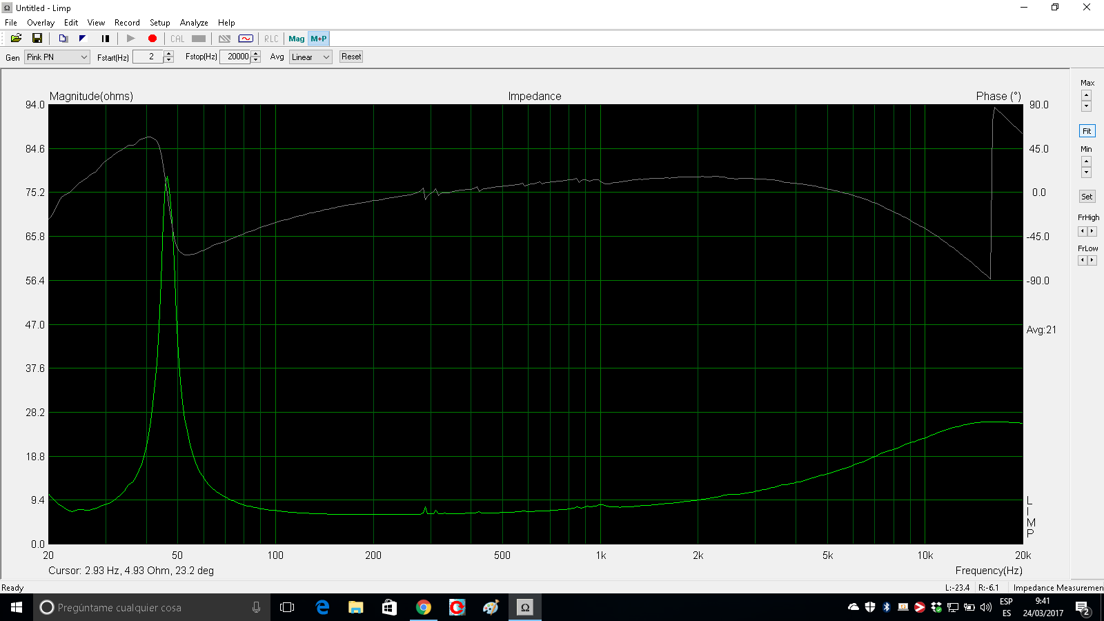
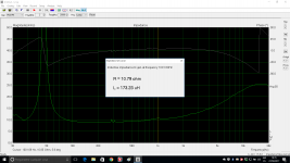
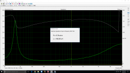
No, with Limp to get the inductance value at a given frequency, left click in the graph area to locate the cursor at 1khz or at your frequency of interest and go to menu Analyse/RLC Impedance Value at Cursor Position.
PD: One question: Why do you insist in using cad tools to make old fashion calculations like getting Le at 1khz? To further linearize the impedance of driver?
You no longer need to do that sort of things with modern tools. Just make good impedance and FR measurements, load those files in Lspcad or similar and let the CAD make the dirty job without simplificated calculations of yestercentury...
Last edited:
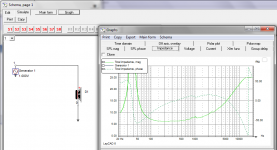
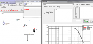
Regarding Lspcad or similar, there is always a learning curve, but the basics are always the same:
- draw a schematic
- load your drivers data files ( both FR and IMP)
- choose a target filter
- try to get useful component values, by guess or using the optimizer
Basically you have to provide good measurement data, and know what you want: TARGET.
- draw a schematic
- load your drivers data files ( both FR and IMP)
- choose a target filter
- try to get useful component values, by guess or using the optimizer
Basically you have to provide good measurement data, and know what you want: TARGET.
Attachments

Confusing figures
It's curious how manufacturers won't strictly specify at what frequency they measure Le. We know that the Xl=sqrt(Z^2-Re^2) so from the manufacturer impedance measurement of SB 23 NRX S45-8, the Z=8,5; Re=5,6 giving Xl=6,39. L(mH)=Xl/(2*pi)
Le=1,017 mH and manufacturer says 0,6 mH!
Seas CA 18 RLY has (traced) at 1 kHz Z=8,53; Re=5,8 giving Le=0,98 mH which is closer to 1,08 mH according to manufacturer.
Try Scan Speak 13m 8640! At 1 kHz Z=8,2; Re=5,8 and it's said to be Le=0,1 mH. By the calculations it is Le=0,92 mH. Let's see how it looks at 10 kHz. Z= 10,4; giving Le= 0,137mH.
Appears they sometimes use the 10 kHz as the reference point.
Attachments
Last edited:
In the context of merlin el mago's question , he has indeed found the correct method of obtaining L and R at a specified freq. from the ARTA/LIMP, impedance and phase graph. There are only three simple calculations to be made and these can be performed very quickly on a calculator in less time than it takes to fill in a CAD program. I am happy he has made such good progress.

In the context of merlin el mago's question , he has indeed found the correct method of obtaining L and R at a specified freq. from the ARTA/LIMP, impedance and phase graph. There are only three simple calculations to be made and these can be performed very quickly on a calculator in less time than it takes to fill in a CAD program. I am happy he has made such good progress.
So why not give him a help yourself?
I am a bit tired of too wise or not wise enough guys!
Troelsgravessen data SB Acoustic 23NRXS-45-8

He used 0.15mH as Le

Merlin, sorry, help yourself, or let somebody else help you, I GIVE UP!

Finding Inductive reactance (Xl)
To calculate Xl from a speakers impedance (Z)
and phase at a specified frequency, the correct equation is Xl=sin theta.Z
The problem that arises is that the resistance and inductance of a speaker are not constants and are variable with frequency and the practise of writing them down as Re and Le causes the confusion. It is up to the accepted authorities such as the AES to remedy this unfortunate situation and change the Unit Symbols to Ref and Lef or another agreed format.
It's curious how manufacturers won't strictly specify at what frequency they measure Le. We know that the Xl=sqrt(Z^2-Re^2) so from the manufacturer impedance measurement of SB 23 NRX S45-8, the Z=8,5; Re=5,6 giving Xl=6,39. L(mH)=Xl/(2*pi)
Le=1,017 mH and manufacturer says 0,6 mH!
Seas CA 18 RLY has (traced) at 1 kHz Z=8,53; Re=5,8 giving Le=0,98 mH which is closer to 1,08 mH according to manufacturer.
Try Scan Speak 13m 8640! At 1 kHz Z=8,2; Re=5,8 and it's said to be Le=0,1 mH. By the calculations it is Le=0,92 mH. Let's see how it looks at 10 kHz. Z= 10,4; giving Le= 0,137mH.
Appears they sometimes use the 10 kHz as the reference point.
To calculate Xl from a speakers impedance (Z)
and phase at a specified frequency, the correct equation is Xl=sin theta.Z
The problem that arises is that the resistance and inductance of a speaker are not constants and are variable with frequency and the practise of writing them down as Re and Le causes the confusion. It is up to the accepted authorities such as the AES to remedy this unfortunate situation and change the Unit Symbols to Ref and Lef or another agreed format.
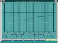
VaNarn, you weren't paying attention to my measurement of SS 13M 8640-00. I didn't photoshop these values! It's real data for the units I had at hands, and Audiomatica Clio calculates as I have already said. I have one book on speaker design, and there is also the same procedure for calculating voice coil inductance at a frequency of our interest. There is no wrong or right formulae! The right triangle mathematics is simple.
edit: I'm attaching original text file measurement, with phase angle.
edit: I'm attaching original text file measurement, with phase angle.
Attachments
Last edited:
I think for a midranger intended to be crossed above 3khz, or for a fullranger, 10khz is a more sensible reference than 1khz, which is a more sensible reference for a woofer or midwoofer.
In the case of the SB 8 incher, sims clearly show that the voice coil inductance has little impact on the transfer function provided you cross <1khz. If crossed >1khz ( not a good idea for bad linearity) the filter need to be damped in some way with a zobel o a resistor.
In the case of the SS midranger, the low Le at 10khz allows simple filtering without ringing side effects to be corrected.
Btw, for lower voice coil inductance above 1khz gives lower distortion in the high mid range. Distortion wise Le at 10khz makes also more sense than at 1khz for a midranger/fullranger.
Some manufacturers like PHL Audio give Le at both freqs:
http://phlaudio.com/no_cache/uk/phl-audio/products/fiche-pdf/index.html?user_productsdb_pi1[uid]=28
But once again if you have your own ZMA data file, why bother with such calculations?
Attachments
Last edited:
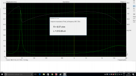
I don't know, since i don't know this driver and each of the last 3 curves you have loaded here are very different. Btw, the curve from the datasheet is totally impossible to read because of absurd scaling. So that...
PD: In post 7 is the impedance curve based on the file you loaded, and it is clearly different from this last curve.
PD: In post 7 is the impedance curve based on the file you loaded, and it is clearly different from this last curve.
Last edited:
- Home
- Loudspeakers
- Multi-Way
- Calculating driver inductance from Limp