
My conclusion about measuring driver voice coil inductance (Le)
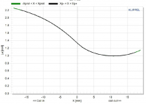
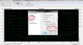
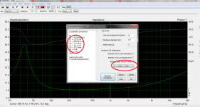
This is a measurement I found an an SBA unit performed on Klippel gear and by the traced data of impedance curve, which was measured with LMS system, it is beyond any doubt that the correct way of acquiring Le value is to calculate the imaginary part of the Z by the phase angle data and use that value to arrive at the result. Klippel doesnt make mistakes. By the graph plotted at the rest position the driver inductance is about 1,3 mH.
Audiomatica got it wrong with the Clio System of the 90's. WT3 does that the same nowadays.
Attachments
Last edited:
Audioxpress October 2015 - Clio Pocket review
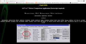
I have found this and my curiosity is satisfied now. The new Clio system now calculates Le of a driver the right way and you can see that from the window where the TS parameters of Usher 8945A stating Le 1kHz=0,26 mH which confirms with Z multiplied by sine(theta).
I have sent an inquiry to Audiomatica and I got the first reply yesterday and am awaiting for the second one. I'll report later when I get the second one, if I get it at all.
You could ask yourself also why did the Audiomatica company obsess over such a small technicality as Le at 1 kHz and 10kHz which is standard data in their TS parameters, which used to be calculated the wrong way ( Clio HR2001 board and software that works in DOS) and the right way with modern Clio boards. Why did they obsess over it and manage to remedy it? Because it's normal to get things done properly and accurately. If you wonder why I am interested in these matters is because I paid for this gear a great amount of money and I am interested in any flaw it might have in itself.
I am not interested in ARTA parameters to get the shape of the impedance. Anyway ARTA calculates Le the same way, by the theta.
I am not interested in ARTA parameters to get the shape of the impedance. Anyway ARTA calculates Le the same way, by the theta.
Last edited:
I am not interested in ARTA models of lumped parameters to get the shape of the impedance right. That's beside the point.
I can also answer you that the point is pointless, and the discussed Le(F) concept quite a poor one compared to better models...

Nothing to call Clio, Arta, Soundeasy, or the AES itself about...
Last edited:
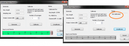
Study the application notes AP1, AP2 and section 6 of LIMP user manual. Is your sound card mentioned in the manual as succesfully tested with ARTA?
I think yes it's M-Audio Mobile-pre USB.
..which used to be calculated the wrong way ( Clio HR2001 board and software that works in DOS) and the right way with modern Clio boards.
Right way? Wrong way? Why bother: it's useless!

If the impedance curve was good before and is still good now, same one, the rest is only bla bla bla...
Last edited:
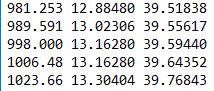
Lojzek is right, the reason I opened this thread is because I found differences between on line calculators and maths calculation to get Le at 1kHz or more. Thanks in special to VaNarn contribution post 7 21.3.2017 http://www..com/forums/multi-way/305547-zobel.html#post5026661 finding the impedance and phase of the speaker at the crossover frequency and solving for R=cos theta.Z and for XL= sin theta.Z http://www.diyaudio.com/forums/multi-way/305547-zobel-4.html#post5028875 The formula given was Cz= Ls/Rs^2. Later clones of this calculation in an attempt to flatten a speakers' impedance use Rdc or Re x 1.25 in attempt to correct for the nominal impedance (Z) of the speaker to suit a crossover network design. By example using a Focal 7N313 where the D.C. resistance is given as 6.1 ohm and the inductance as 0.38 mH ( at 1 kHz ?) the first formula gives Cz as 10.21 mFd and the latter as 6.536 mFd. Using the method outlined in my first post the impedance at 3.5 kHz ( the desired xover freq.) was found to be 10.34 ohms with a phase angle of 28.65 degrees. This gives the effective resistance as 9.0742 ohms and the inductance as 0.2254 mH . Calculating for a network to give an impedance of 8 ohm with the phase at 0 degrees in conjunction with the speaker, resulted in values of 10.67 ohm and 3.69 mFd. It is a pity that many sources still keep quoting the wrong method of correction and so many people have been caught by this misapplied Zobel network.
Hi there,
What formulas did you use to calculate L2 and C2?
I have found equations for Res and Lces but not for L2 and C2
What formulas did you use to calculate L2 and C2?
I have found equations for Res and Lces but not for L2 and C2
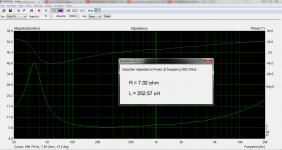
I got for that data in my simple impedance fitting spreadsheet...
Fs=120
Qts=0.59
Qes=0.68
Cmes=0.000148
Lces=.01186
Res=37.8
L1=37uH
R1=6.1ohms
L2=.34mH
R2=2.4ohms
L2 and R2 are in parallel, in series with L1 and R1, these model the lossy inductance
The formulas that are of interest are covered under Electrical Impedance via
www.bodziosoftware.com.au/BChapter_3.pdf
www.bodziosoftware.com.au/BChapter_3.pdf
- Home
- Loudspeakers
- Multi-Way
- Calculating driver inductance from Limp