Yes, exactly. I should have been more explicit on the idea. Basically take a vertical AMT driver and compress it into a square or circle. I don't know if I'm thinking about it correctly but couldn't a rather tall driver be used? The height would impact the relative arrival times though around the square.
In my head it would allow for a very large surface area, very light diaphragm, boosted lows for better extension and reduced comb filtering and beaming. Of course nothing in audio is free so I'm probably missing something vital. I think the key is what the wavefront looks like and I'm not sure I have a handle on that.
In my head it would allow for a very large surface area, very light diaphragm, boosted lows for better extension and reduced comb filtering and beaming. Of course nothing in audio is free so I'm probably missing something vital. I think the key is what the wavefront looks like and I'm not sure I have a handle on that.
An externally hosted image should be here but it was not working when we last tested it.
I'll have to give it some thought, but I think that might work! And then you could use BG drivers on a horn.
Picture a Paraline flipped upside down. The Paraline takes the rectangular wavefront and transforms it into a square wavefront. And then the square wavefront feeds the horn.
It could be used at any point along the horn - not just the throat.
For instance, you could use a Fountek ribbon at the throat and a BG Planar for the midranges.
Now some might think "why bother", but there are a couple reasons:
1) Really flat impedance
2) planar drivers have low distortion because of their large surface area
The drivers aren't cheap, but for a lot of my projects I'm willing to spend a little extra to save space, and planars are tiny
No, the output is uniform from top to bottom.My thinking is that it would simply have the opposite effect. IIRC the paraline that goes from circle input to horizontal output with equal pathlengths is in phase from top to bottom but attenuated more at the extremes than the middle. Is that right?
Taking a planar driver, which the Paraline emulates (but by virtue of using compression drivers which have more displacement per diaphragm area than planars and can achieve a lower cutoff frequency) then mashing it through a Paraline so it then comes back out with a hemispherical radiation (like a compression driver) is the most backwards thing so far proposed in this thread.
With a planar source, just do like Peavey (or Paul's center channel) does with their line arrays, put waveguides on them and cross them high enough where their limited displacement is not a problem. If you want a wider vertical pattern, just have the planars describe an arc.
Last edited:
Exactly my thoughts PB. I was thinking AMT or even RAAL for HFs and something like a giant AMT or the BG mids fed into the synergy. Not cheap, but could be pretty high performance.
The width of the driver would need to be <1/2 the highest wl produced because it would effectively be split into two 1/4 wl sides.
So a pair of NEO10s covering 300hz-1500hz with an AC AST30100 handling above 1500hz. The NEO10s would need a paraline with channel depth of no greater than 2". The mids would enter on the horn walls to form a Synergy of whatever shape is desired. Not cheap, but a pretty wild way to combine the benefits of a ribbon style driver into a horn.
The reason that this works is that the ideal shape for the entrance to the horn is a point or a ring.
Hi John, This isn't true and I think that you know that. It's statements like this that make me wonder "Where's the beef!?"
The "ideal shape" depends on the waveguide and I know of none that want a point or a ring. Well, a point would be OK for a conical waveguide as long as the throat went down to a very small aperture (very impractical). But I know of nothing that "wants" a ring.
No, the output is uniform from top to bottom.
Taking a planar driver, which the Paraline emulates (but by virtue of using compression drivers which have more displacement per diaphragm area than planars and can achieve a lower cutoff frequency) then mashing it through a Paraline so it then comes back out with a hemispherical radiation (like a compression driver) is the most backwards thing so far proposed in this thread.
With a planar source, just do like Peavey (or Paul's center channel) does with their line arrays, put waveguides on them and cross them high enough where their limited displacement is not a problem. If you want a wider vertical pattern, just have the planars describe an arc.
Well, it sounds like I deserve an award from coming up with the most backwards idea in the thread.

There certainly might zero point to my proposal. It was just a thought. I guess you could simply use an AMT as the HF driver in a synergy without the trouble of a paraline.
No, the output is uniform from top to bottom.
uh uh
The output is concentrated at the center.
This is a 'feature' or a 'defect', depending on how you look at it.
On the upside it makes it easier to array.
On the downside, I'd anticipate that peaks and dips would be more intense at the center than at the edges, because horns get peakier the smaller that you make them.
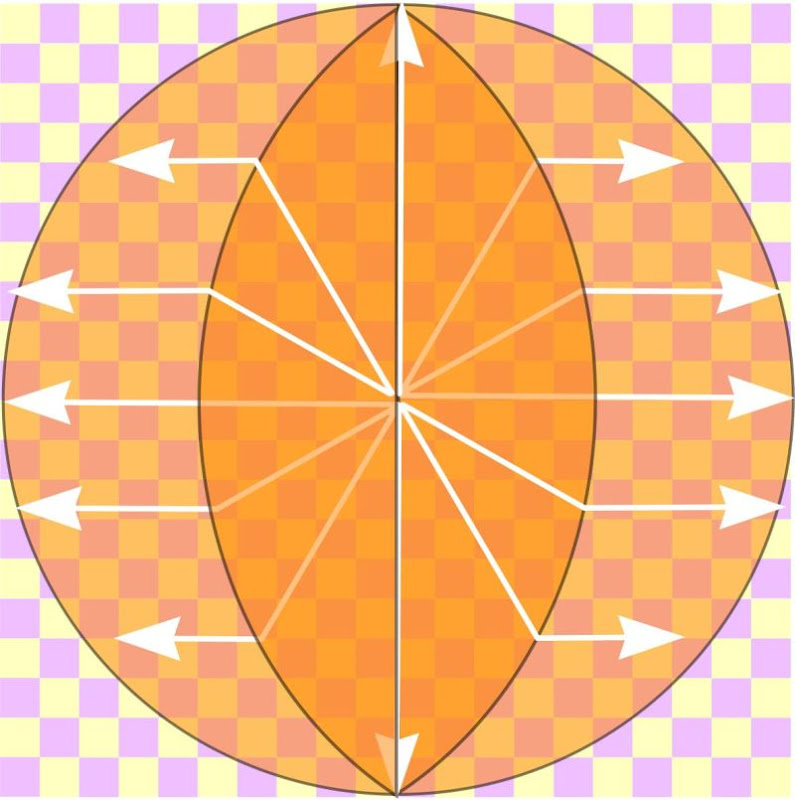
The output is concentrated at the center because of the way the output is redirected in the correction slot. In my illustration above you can see how the 'rays' are concentrated at the center of the exit of the Paraline.
Conversely, if one built a 'Paraline in reverse' you'd find that the output at the center of the exit (which used to be the entrance) would be attenuated.
Danley was the one that clued me into this, a year ago, on page 2 of "Sunshine"
"One other less obvious thing is that as the sound radiates away from the driver, the spl is falling according to area. This means with a constant thickness, the top and bottom are automatically -3dB relative to the center. The wider the vertical pattern angle, the greater the amplitude shading the center relative to the ends"
Does that make sense?
Given the analysis that you just gave, nothing that has directivity could be phase coherent because it is the phase shift from different points on the wavefront that creates a directivity. A point source is phase coherent and also has no directivity. Nothing else will do that.
An OS waveguide has complete coherence of the phase within its radiation pattern, but the coherence falls away exactly as the amplitude falls away - they are basically one and the same thing. Within the radiation pattern of an OS waveguide the wave appears to have come from a single point located at the center of the waveguides throat aperture. Outside of its design pattern (the walls) the wave is in the shadow zone of the devices walls, i.e. the center of the throat aperture is no longer in the line-of-sight and the wave has diffracted to get to those field points - hence it is no longer a coherent wavefront.
Well, it sounds like I deserve an award from coming up with the most backwards idea in the thread.
There certainly might zero point to my proposal. It was just a thought. I guess you could simply use an AMT as the HF driver in a synergy without the trouble of a paraline.
Art Welter and Earl Geddes are vying for 'biggest bully on diyaudio'
I don't mind though, I've met Geddes in person and he's one of the most enthusiastic and patient teachers I've met. Sometimes the smartest guys on the forum come off a little, uh, "abrupt"
The first time I ever emailed Geddes he called my idea "absurd"
It basically made me want to go in the garage and built it to prove him wrong
If anyone reading this thread wants to learn about how the Paraline works, read the CBT papers.
I've read all these papers, even the JASA ones on which the CBT is based and I simply do not see any connection to the paraline. I am completely lost on all of this discussion because none of it adds up - its not "sound" science.
Art Welter and Earl Geddes are vying for 'biggest bully on diyaudio'
I don't mind though, I've met Geddes in person and he's one of the most enthusiastic and patient teachers I've met. Sometimes the smartest guys on the forum come off a little, uh, "abrupt"
The first time I ever emailed Geddes he called my idea "absurd"
It basically made me want to go in the garage and built it to prove him wrong
I'm not worried about it. I thought it was funny. I was really just throwing out an idea that popped into my head. I've just been trying to figure out ways to use the paraline concept in HiFi settings.
I've read all these papers, even the JASA ones on which the CBT is based and I simply do not see any connection to the paraline. I am completely lost on all of this discussion because none of it adds up - its not "sound" science.
Unity and Synergy horns are attempting to generate a segment of a pulsing sphere. If you were able to array a pile of Danley SH-50s into something that looks like a Death Star, it would come pretty close to spherical radiation
The CBT and the Paraline basically make no attempt to control radiation in the third dimension. Both are attempting to radiate a ring-shaped wavefront.
The 'twist' in the Paraline is that it takes that ring, reflects it through a 'correction slot', and produces a flat wavefront.
A spherical wavefront IS a curved wavefront - what's the difference?(Because the LC can generate a spherical wavefront, while the Paraline can only generate a flat or curved wavefront.)
All waves are three dimensional, but sometimes one of the dimensions is too small to be a factor - like at the junction between a compression driver diaphragm and the phase plug. In this case the wave can be thought of as moving in only two dimensions. The same would be true of what I understand the paraline device does when the two plates are close together. But once the wave meets with the horn it becomes three dimensional and has to be considered as such. There are no longer any constraints on its motion and it will move in all three directions at the same time. This means that at the opening of the paraline the wavefront IS three dimensional just as it is in the throat of any other phase plug at this point. If the path lengths to get to that aperture are not equal then the wavefront in the aperture will be curved - this could be good but it could also be very bad. That's because to get a constant curvature to the aperture wavefront the path length differences have to be frequency dependent - and that's not possible. So while the paraline might create a good spherical wavefront at some frequency it is not going to be so at some other frequency.
Only when the sound channels have a constant length can a spherical wavefront be created that is independent of frequency (or more nearly so) this is why the length of the channels in a phase plug is so critical.
The ability to alter the shape of the aperture wavefront by manipulating the phase plug is well covered in my patent on the same topic. there is only a limited amount that one can do.
The 'twist' in the Paraline is that it takes that ring, reflects it through a 'correction slot', and produces a flat wavefront.
I'm sorry John, but that's just hand waving - I don't believe it. Maybe at one frequency this might be true, but not broadband, it can't be true.
I'll bow out of tis discussion if you want to wave your hands about and prophesize on the virtues of good marketing, but if you want to know what is really happening you need to consider some more complex stuff. I'm trying to point out what that "stuff" is.
Last edited:
Hi John, This isn't true and I think that you know that. It's statements like this that make me wonder "Where's the beef!?"
The "ideal shape" depends on the waveguide and I know of none that want a point or a ring. Well, a point would be OK for a conical waveguide as long as the throat went down to a very small aperture (very impractical). But I know of nothing that "wants" a ring.
When I say that "the ideal shape for the entrance to the horn is a point or a ring" I should probably clarify the term "horn"
When I say "horn" I'm including everything all the way up to the diaphragm. So when I say "horn" I mean "the entrance to the Paraline" which I consider as part of the horn.
If we're talking about the transition from the exit of the Paraline to the entrance of the "horn", then NO, a flat wavefront is NOT ideal
Feeding a horn with a rectangular wavefront, like most Paralines do, is fraught with all kinds of issues. You're going to get high frequency comb filtering which will vary depending on whether you're on axis or off-axis. You're going to get problems with the phase response because the distance from the listener to the exit of the Paraline will vary from the top to the bottom of the Paraline.
So, yeah, all kinds of issues here.
BUT -
The Paraline can do some neat things if you know how to engineer around them. (hint: curve the wavefront)
Most of my audio projects are SEVERELY space limited. They go into cars and they go into a living room where my GF won't tolerate big speakers. And in that context, I can live with the shortcomings.
I'm sorry John, but that's just hand waving - I don't believe it. Maybe at one frequency this might be true, but not broadband, it can't be true.
I'll bow out of tis discussion if you want to wave your hands about and prophesize on the virtues of good marketing, but if you want to know what is really happening you need to consider some more complex stuff. I'm trying to point out what that "stuff" is.
Just take a look at the CLF data.
Does a Paraline give you a perfectly flat wavefront?
No, not perfect, but it's definitely having a effect. The CLF data on the VTC boxes isn't as picture-perfect as the CLF data on the SH-50, but it's doing what it's supposed to.
Just sit down with the CLF viewer for an hour or so and you can see what it's doing. The CLF data on all the Danley horns has been available for years.
Only when the sound channels have a constant length can a spherical wavefront be created that is independent of frequency (or more nearly so) this is why the length of the channels in a phase plug is so critical.
Correct me if I'm wrong but I believe a Paraline has (or can have if built to a certain shape) equal pathlengths from the entrance to the exit of the Paraline.
A spherical wavefront IS a curved wavefront - what's the difference?
All waves are three dimensional, but sometimes one of the dimensions is too small to be a factor - like at the junction between a compression driver diaphragm and the phase plug. In this case the wave can be thought of as moving in only two dimensions. The same would be true of what I understand the paraline device does when the two plates are close together. But once the wave meets with the horn it becomes three dimensional and has to be considered as such. There are no longer any constraints on its motion and it will move in all three directions at the same time. This means that at the opening of the paraline the wavefront IS three dimensional just as it is in the throat of any other phase plug at this point. If the path lengths to get to that aperture are not equal then the wavefront in the aperture will be curved - this could be good but it could also be very bad. That's because to get a constant curvature to the aperture wavefront the path length differences have to be frequency dependent - and that's not possible. So while the paraline might create a good spherical wavefront at some frequency it is not going to be so at some other frequency.
Only when the sound channels have a constant length can a spherical wavefront be created that is independent of frequency (or more nearly so) this is why the length of the channels in a phase plug is so critical.
The ability to alter the shape of the aperture wavefront by manipulating the phase plug is well covered in my patent on the same topic. there is only a limited amount that one can do.
All of this makes sense, except for one thing. You say "to get a constant curvature to the aperture wavefront the path length differences have to be frequency dependent - and that's not possible." I agree that it's not possible to have a pathlength in the Paraline which is frequency dependent. (Because the speed of sound is constant with frequency.)
But I don't understand WHY the path lengths would have to be frequency dependent.
As for all the other pieces, YES I agree that the radiation will go from two-dimensions to three dimensional at the exit of the Paraline and the entrance into the conical section of the horn. And at that transition, YES the wavefront will basically suffer from some serious self interference, because it's only constrained by the sidewalls. (Art noticed that he could remove the top of the conical section of the horn, with virtually no effect.)
Correct me if I'm wrong but I believe a Paraline has (or can have if built to a certain shape) equal pathlengths from the entrance to the exit of the Paraline.
It could - almost - but not the way it is being drawn or discussed here. In those cases the path lengths all vary and that can be problematic.
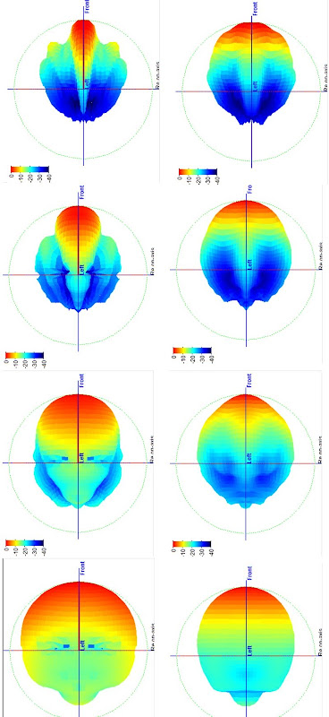
John - I don't look at CLF data as this is not a very attractive way of looking at how a speaker works. Its useful in the modeling programs, but not for looking at performance as a "broadband speaker unit". More and more people are posting polar maps - now those are useful and show all the problems at a single glance (as long as they arn't normalized, which just rescews everything back to where you don't know what is going on.) I'd love to see the Danley stuff in this format. I'd love to see it posted on my website in my polar program so that we could all see exactly what is going on. Some years back he alluded to providing that information but it never happened.
- Home
- Loudspeakers
- Multi-Way
- Square Pegs