Astro-Muse,
Yes, it will work. By mono, do you mean bridged? Is this a feature built in or did you modify to make it bridged? If you modified it, then you know enough to complete the servo conversion. The conversion I describe will work with a bridged amplifier. I have numerous friends using this simple design with bridged amplifiers.
For a variety of design considerations (including stablity with unknown amplifiers) I chose 6 db of MFB global feedback. To achieve 6 db, one must find out the value of the series feedback resistor in the stock amplifier. The value of the series resistor in the amplifier feedback voltage divider network is the value of the resistor you add in series to the sensor voice coil lead (hot side). You do need to know your amplifier well enough to determine the values of its feedback voltage divider network. This does take some electronic knowledge.
tiroth,
The "phase" difference you see in box is because fo the box/system resonance. You want to correct the frequency response and "phase" errors with the feedback.
There is a problem with the idea of phase shifting in the transient coherent world. The sounds we listen to are never sine waves. The sounds we listen to are always starting and stopping and even when they cycle, one iteration is never exactly the same as the one before.
The "phase" problem one sees in the sensing coil output is that of the signal lagging the input. When you introduce another "pole" or use an integrator/differentiator you can only add more lag. While it may look like it matches when testing with a sine wave, with a coherent transient you have made the error worse. The feedback signal you are trying to use to correct the response of the driver is farther behind the signal you need to correct. This is a problem with a sensing voice coil or with an accelerometer.
Yet, as tiroth found, unless there is a problem (such as system resonance), the lag off of MFB sensing is not critically. The function of the MFB is to correct this driver lag of the input signal (and to suppress the decay overhang of the driver).
Mark
I have a dual voice coil sub which I drive with an old stereo amp driven in mono. Would this system work on any amplifier? How do you determine the values of the resistors?
Yes, it will work. By mono, do you mean bridged? Is this a feature built in or did you modify to make it bridged? If you modified it, then you know enough to complete the servo conversion. The conversion I describe will work with a bridged amplifier. I have numerous friends using this simple design with bridged amplifiers.
For a variety of design considerations (including stablity with unknown amplifiers) I chose 6 db of MFB global feedback. To achieve 6 db, one must find out the value of the series feedback resistor in the stock amplifier. The value of the series resistor in the amplifier feedback voltage divider network is the value of the resistor you add in series to the sensor voice coil lead (hot side). You do need to know your amplifier well enough to determine the values of its feedback voltage divider network. This does take some electronic knowledge.
tiroth,
Unfortunately phase issues were a bigger problem than I had expected. Open-baffle, the phase differences between the input signal and the voicecoil measurement were fairly negligable, but in a sealed enclosure the phase shift was 90 degrees at the frequencies of interest. I chose to correct this about 30Hz via a capacitor and found that the voicecoil signal could be made to match the input EXACTLY.
The "phase" difference you see in box is because fo the box/system resonance. You want to correct the frequency response and "phase" errors with the feedback.
There is a problem with the idea of phase shifting in the transient coherent world. The sounds we listen to are never sine waves. The sounds we listen to are always starting and stopping and even when they cycle, one iteration is never exactly the same as the one before.
The "phase" problem one sees in the sensing coil output is that of the signal lagging the input. When you introduce another "pole" or use an integrator/differentiator you can only add more lag. While it may look like it matches when testing with a sine wave, with a coherent transient you have made the error worse. The feedback signal you are trying to use to correct the response of the driver is farther behind the signal you need to correct. This is a problem with a sensing voice coil or with an accelerometer.
Yet, as tiroth found, unless there is a problem (such as system resonance), the lag off of MFB sensing is not critically. The function of the MFB is to correct this driver lag of the input signal (and to suppress the decay overhang of the driver).
Mark
Maybe not!
I didn't bridge the amp Mark. It hasn't been equiped with that feature and I'm not certain there would be an advantage to doing it when I have a dual VC sub. I have just used the mono switch. I'm not certain where to find the series feedback resister in my amp, so maybe I'd better steer clear of this project, as tempting as it sounds.
Let us know if you ever publish a detailed article on the web. Maybe I could follow it if there are lots of detailed diagrams (lol).
MarkMck,
Thanks for your comment. Ironically I came to this realization as well on the bus home when I stopped to really think about the impossibility of it all (Insert foot in mouth)
I hooked up my original filter-free circuit again and although the feedback is certainly operating, I don't get any measurable distortion reduction.
I then took a look at a FFT of the VC output, and found the distortion was about 10dB down from the acoustic distortion. Bingo.
For reference Shiva, sealed Fb=38Hz, signal 31.5Hz @ 25W, acoustic -32dB 2nd harmonic, VC -42dB 2nd harmonic. Feedback 6dB. (Circuit is a bit of a lashup and isn't stable above that)
I'll try to take another look at this soon with measurements above resonance, although that is purely academic for me.
Feels right to me too. With a sinewave signal, the peak of the waveform (maximum voltage) corresponds to the zero-crossing of the voice coil (maximum velocity). So it would seem the voice coil movement lags the drive voltage by 90 degrees. Over-simplification?Konrad said:Hello
I think one of the main things to do first, even before trying to apply feedback is to make the amplifier a current amplifier. The pahse is therfore changed 90* in our favor at high freq, and higher bandwith is possible.
There are several papers deskribing simple mfb. This i probably one of the best:
http://www.egr.msu.edu/~radcliff/LabWebPages/home/papers/SpeakerFB.pdf
http://www.egr.msu.edu/~radcliff/LabWebPages/home/papers/SpeakerFB.pdf
Konrad,
Thank you for the article link. I had not read this article before. The authors, however, use the second voice coil as a sensor. As I quickly scan the article it appears they found no significant problems with the sensor signal below 70 Hz. They did find problems above 70 Hz and they used a second order filter for frequencies above 70 Hz.
My research has not duplicated the problem they describe above 70 Hz. Plus, within my design concept, and since I am only using the woofer up to 100 Hz my focus was on the performance near resonance. This is where the distortion and decay overhang are most problematic.
The intent of my posting was to provide a starting point, both in concept and implementation. I wanted to provide documentation to demonstrate what the technique could provide.
There is nothing wrong with using the technique as described. It works and it will improve the performance of a woofer at low frequencies. Yet, as a progressive society, we are always trying to do better. As stated in the article there are limitations to the technique. Improvements are possible. Complexity, however, must increase. My little project requires only one resistor, one wire and a couple of soldier connections. Sometimes the increase in complexity is a small increase and sometimes it is not. Any change, however, must be tested to see if the design criteria are being achieved.
Within those considerations, I encourage DIY folk to think, to experiment, and to implement other designs. And if you are motivated to do so, please share as much detail as you can.
I wish all of you great fun as you think, experiment, and implement.
Mark
Currently adjusting my new circuit with accelerometers. There the possible feedback increased as the amplifier driving the speaker was made current feedback. There is limmits for the current fedback, open loop etc. but more of it seem to improve performance for the total circuit.
A real element is 3.rd order, makes the PID (Proposjonal Integrator Derivator) circuit more difficult to make and adj. But after all current feedback has near the same freq response above elements resonance. Then i think integration from the resonance and down. Then a small amount of D but high i mean 100-300 hz region as D also improves phase you dont want to much at low or resonance as fase is ....... Therfore i vant to know: How abt a BIQUAD filter in front of the amplifier, here the adjustments have better range ? compared to PID? ( P= K proposjonal gain)
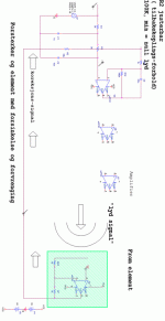
More of links. And my scetch drawing
http://www.danmarx.org/audioinnovation/servosub.html
Merry xmas
http://www.danmarx.org/audioinnovation/servosub.html
Merry xmas
Attachments
Making The amplifier a current gain amp :In this example the element's "Q" at resonance is high, thus high voltage output is needed. So there is still a kind of requierements for high power (Voltage swing) amplifiers. To lower this "Q" the volume of the kabinett neads to bee increased. but this will lower q only to a certain ekstent.
Current drive removes phase problems :
Current drive removes phase problems :
Attachments
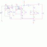
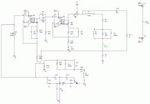
The "conjungate nettwork" C10 R17 is there to increase stability.
C9 R16 is there to increase fase margin near elements resonance.
In my case im using buffered accelerometer inserted at R14, and the R14 repleased with 3k and 10u series cap.
As the current is the force needed to corect for distorted acceleration the phase of the current is important as this also gives/tell us the direction of power
The fase in the current drive circ:
Attachments
As for the voltage feedback at the secondary coil of dvc elements the phase shift at resonance needs to bee compensated for. It will then bee somthing near the nettwork attached to R14, L4 beeing the secondary voice coil.
Alternative is replacing the nettwork with a "doble T filter" as this can bee made a good aproximation to the "stupid" values in the compensating nettwork.
Alternative is replacing the nettwork with a "doble T filter" as this can bee made a good aproximation to the "stupid" values in the compensating nettwork.
Attachments
Splitting R10 so to apply current drive from resonance, and voltage drive below vil make the possibility to increase gain at lower freq and thus more feedback
(R10 series cap redused to below 10u and from amp negative input to gnd same value as R10 and a "larger" cap ) This wil then become a sort of "power drive" Bee carefull use fuses in the circuit wile testing!!! as gain is gain is high.
So i realy think it is possible to make good aproximations by some meashurements and a litle simulation.
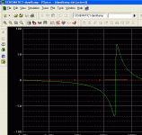
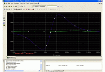
fase of T filter :
Attachments
Designing Motional Feedback Loudspeakers
I did a fair bit of work on this subject, using dual voice-coil speakers, and I would like to share it with you. I will need to do a few posts, so please be patient. Tell me what you think, it aint perfect, but it is simple, suitable for DIY.
The first thing with a feedback system is to ensure that it's stable. At low the low frequencyend I direct-coupled the amp. The only phase shifting device at low frequencies is then the loudspeaker itself. At high frequencies I had to start the roll-off at 1kHz. With these precautions, the d.c. open-loop gain of my system is about 150dB, and it’s perfectly stable.
The analysis of a speaker system can get very complicated. At the time I had neither a computer nor sophisticated test gear, so I adopted a different approach.
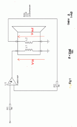
In the attached image, the gain equation is the same as that of an op-amp. The gain is set by the feedback transducer, whatever that may be, rather than the pair of resistors usual in an op-amp circuit. As in that case, when the open loop gain, A, is very large,
The equation becomes;-
Gain = 1/
End of part 1
Gain = 1/B
Attachments
Part 2
Computers can do anything - Except what you want.
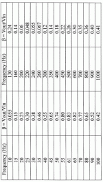
I measured Vout and Vin at various frequencies using my sig. gen. and ‘scope, and calculated â for each frequency. The results are given in the table below.
The maximum feedback voltage occurs at 61Hz, the bass resonance of the speaker mounted in its box. This gives maximum damping at resonance, which is what we want. The problem is what happens when the feedback voltage is small? The system gain becomes large, and the response peaks at very low frequencies and at the minimum impedance frequency, 220Hz in my case. The size of these peaks is proportional to the open loop gain.
If current feedback is added to the voltage feedback, then when the feedback voltage is small, the current will increase, and the voltage developed across the sensing resistor will prevent the peaks. Previous posts have suggested using current feedback,
but how much?
Sorry guys, but you’ll have to wait for the next instalment. I have to convert the next diagram.
I'm new to this posting lark, but it's fun, I think
Attachments
Part 3
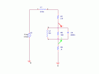
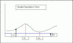
I have attached a freehand sketch of the usual speaker impedence curve to illustrate the following points;-
Fs is the usual mass- compliance resonance of the speaker in a box. It is a parallel resonant circuit with a maximum impedence at resonance.
Fm is the mass-inductance resonance. It is a series resonant circuit with a minimum impedence at resonance.
The phase shift at both Fm and Fs is therefore zero.
The e.m.f induced in both driven and feedback coils due to motion must be the same, the coils are identical and they move together in the same magnetic field. The impedence curve reflects the induced emf. If we assume that the errors are small, we can write;-
B = (Z-Re)/Z
There are problems because of the phase shift in Z, it should be a vector subtraction, but if only two points are chosen, Fs and Fm, then phase shift is not a problem. This is good, only two measurements
The expression above can then be used to combine the gain due tocurrent -feedbakk with the original expression for gain due to feedback from the second voice-coil.
An expression for the complete system can then be derived.
Attachments
- Status
- This old topic is closed. If you want to reopen this topic, contact a moderator using the "Report Post" button.
- Home
- Loudspeakers
- Multi-Way
- Simple MFB woofer project
