jaes article
You've got mail!
Now that I am going to try this ace bass technique, despite having unfavourable past experience of this kind of thing, is there anyone who will try my design?
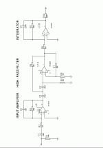
Here's the integrator and input sections.
phase_accurate said:You can mail me your address and I can send you the according JAES article by snail-mail.
Regards
Charles
You've got mail!
Now that I am going to try this ace bass technique, despite having unfavourable past experience of this kind of thing, is there anyone who will try my design?
Here's the integrator and input sections.
Attachments
Measurements at last
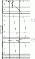
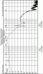
My Praxis system is working now, except distortion for some strange reason, so here are some measurements of the system.
I was surprised at how accurate my original measurements were, considering the equipment I had at the time.
I built a stereo pair, the resonant frequency of one is 61Hz, and the other is 64Hz.
I modelled the drive units is WinISD to see what they would be like un-aided. The resonant frequency in the 45l box (each unit has 22.5l) would be 64Hz, with a Q of 0.617. WinISD recommends a reflex enclosure for them.
Here's the TS parameters, only one coil on each unit used.
Attachments
More....
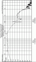
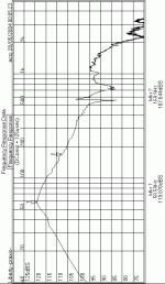
I want to show the effect of changing the ammount of current feedback. Rather than change the value of the current sensing resistor, R8 in the diagram of post#41, I changed the value of R2 to 11K, and inserted a 47K preset pot so that the value could be "tuned".
This is with R2=11k, too much current feedback.
Attachments
more & more
The shape of the curves is the important thing. The gain changes as you would expect. Praxis thinks it's a normal speaker, and calculates it's sensitivity from sound out/volts in. In this case, I'm using the input to the system as the reference for the volts in.
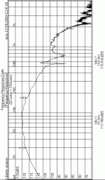
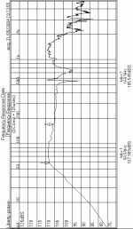
The following is a bit of a surprise. In the equations, if Rs=Re then the B terms cancel, so I thought it would be the response without feedback, But when I replaced R8 (current sense or Rs) with a 3R3 resistor, I got this.....
Attachments
last for now...
The peak in the last one was at Fs. Curious. Any ideas?
When I "tuned" the pot to give the flattest response, guess what? I got 22k!
So I think that maybe the errors due to inductances cancel or something. It shows that this technique works
You will have noticed a slow downward trend towards the lower frequencies of about -3dB/octave. Dunno what that is. It isn't a measurement artefact, because I noticed it with the first plots made with sig gen and scope and electret insert mic. It's not the room either (different rooms) Leaky integrator? Dunno. Any ideas?
Ok let me know what you think.
I'll post distortion measurements when I sort the problem out. The residual distortion is <0.003% above 45Hz, but rises below that to 28% @ 10Hz, this would cloud any subwoofer measurements, so they'll have to wait for now.
The peak in the last one was at Fs. Curious. Any ideas?
When I "tuned" the pot to give the flattest response, guess what? I got 22k!

So I think that maybe the errors due to inductances cancel or something. It shows that this technique works
You will have noticed a slow downward trend towards the lower frequencies of about -3dB/octave. Dunno what that is. It isn't a measurement artefact, because I noticed it with the first plots made with sig gen and scope and electret insert mic. It's not the room either (different rooms) Leaky integrator? Dunno. Any ideas?
Ok let me know what you think.
I'll post distortion measurements when I sort the problem out. The residual distortion is <0.003% above 45Hz, but rises below that to 28% @ 10Hz, this would cloud any subwoofer measurements, so they'll have to wait for now.
It's The Integrator!
Of course, when the feedback cancels in the case when Rs=Re, the output is no longer proportional to velocity. The integrator skews he shape of the curve.
Below is a plot of the system without the integrator, with R8=3R3. A much more familiar result.
Of course, when the feedback cancels in the case when Rs=Re, the output is no longer proportional to velocity. The integrator skews he shape of the curve.
Below is a plot of the system without the integrator, with R8=3R3. A much more familiar result.
Attachments
Re; waste of a thread....
Well I think it's interesting..... but it looks like I am alone in this.
I was inspired by a review of Tannoy's 625ALF subwoofer, which in turn was the product of Hawksford & Mills current driven loudspeaker paper.
Of course, I got the whole thing backwards. It was only recently that I saw their paper, I was trying to work backwards from their finished product. It does work though, and my analysis is so much simpler than theirs, but no less valid.
I have some more stuff to add, but I thought interest had dried up. Maybe I'll post it then...
Have a closer look at this abt speaker eqations:
Eq (D6) in this link.
Then compare to EQ (1) (2) (3) in UAF 42 datasheet
Finaly use inverted konfiguration. And sum Hp Bp Lp with gains as to fit driver eq.
using accelerometer the input is a, if a is like a funktion of sinus integrating gives cos, integrating again gives -sin. and summing sin and - sin is 0. or to say rather perfekt. So summing with corect phase and gain is important (obvius).
Optical position
I saw in Wireless world (late 1970's early 80's) a little circuit for picking up the driver displacement with a photo diode and a infra-red led. The author speculated that the square law reduction in light would be reasonably linear over the displacement of a loud speaker.
Unfortunately the photo copy from the article is still in my parents house in the Uk. have any of you tried this idea?
I did this in the mid 90's using a throw away driver, it worked quiet well, at first then I hooked up the feedback in the wrong phase and destroyed the driver.
Being a student that was the end of my budget. This said ever since I have wanted a motional feedback system as when it did work the bass was better than anything I have heard since.
Late to the party.
In post #41, I saw a circuit diagram seemed to be mixed (voltage and current) feedback. Except for the dual VC of the driver, it looks very similar to the circuit here:
Variable Amplifier Impedance
What's the difference?
In post #41, I saw a circuit diagram seemed to be mixed (voltage and current) feedback. Except for the dual VC of the driver, it looks very similar to the circuit here:
Variable Amplifier Impedance
What's the difference?
Also late to the party, but I've been studying and using motional feedback subs based on Werner's JAES 1957 (?) article for more than 40 yrs.
Funny, sometimes I read a musician writing about a piece and I haven't a clue why they are talking that way about what I hear as a non-musician. Same here.
From my amateur view, we are looking at whether the voice coil or dust cap of the driver is moving just like the electrical signal. When it doesn't, feedback (some mix of voltage and current, positive and negative) grabs the voice coil and makes it behave better.
The back-EMF is the error signal. It is closely tied to the motion of the cone and it ought to be the same as the input signal to the driver. When it isn't due to resonances or non-linearities of the primitive stuff cone drivers are made of... well, that is why it is called the "error signal."
You can "find" that kernel of that error signal by comparing the input to the whole cone impedance. For example, you can treat the voice coil as an element of a bridge which cancels/balances the static parameters of the voice coil.
If the amp acts as if it's output impedance is the mirror image of the driver, that's what you get. Yes, if the do the algebra, the amp looks like a negative impedance. No kidding, but that is the case.
We use the voice coil as a feedback reference point because that is about as close as we can get to thinking of the actual sound output. We can't use a mic in a feedback loop of this sort, for obvious reasons.
Which is why when I read above about using reflex or OB cabinets, I am puzzled. The output of those systems in low freq areas where MF is meaningful and feasible becomes pretty disconnected from the actual motion of the cone.
For many decades, much of the progress of electronics lay in applying feedback. Very peculiar that the last loop - around the speaker - has gathered as little interest as it has.
Last edited:
Hello CLS and bentoronto,
This thread mixes two concepts Amplifier Impedance bass enhancement and Motional feedback.
Your Variable Amplifier Impedance is probably clearer text on current feedback etc.
The other half of this thread discusses motional feedback, where instead of just applying feedback in the electronic domain, feedback is taken around the position of the loudspeaker code, theoretically reducing distortion.
Their are three types of sensors, positional, velocity based, and acceleration based.
with only acceleration, you dont know the velocity of the cone. With the velocity of the cone, you can estimate accurately the acceleration, my measuring the rate of change, (or differentiating). With positional sensors, you can measure the cone position, and by measuring the rate of change, the velocity, and again velocity can me measured in its change and lead to acceleration.
Force = Mass * Acceleration.
Force is proportional to signal current, and assuming the speaker code is a perfect resistor an accelerometer, within a band pass may be in phase with with the current driving the speaker.
What would be much more impressive would be a positional feedback device with an audio processor that processed the incoming signal and used this positional feedback to prevent the speaker reaching non linear behavior or destroying its self, and removing distortion.
In theory simple analogue feed back could in theory provide the benefits of the audio processor over a range of octaves, unfortunately phase changes in feedback make this difficult at resonances even with positional feedback.
True motional feedback speakers are very rare and audiophile Cult items. If their was not a reason for this, (and I suspect setting up costs and the until recently high costs and poor quality of digital processing)a world containing active pro monitors would be using motional feedback. This said while I had one working, (about 30 mins) and increased the feedback the bass sounded subjectively less resonant and more how I would imagine a live bass instrument being played by a fast musician would play, but its a long time ago and maybe effected with the pink sunglasses of memory.
Maybe some manufacturers are using motional feedback for sub woofers in a low end market, using cheap accelerometers to reduce box size and below resonance distortion to acceptable levels. Does anyone know of subwoofer manufacturers using, positional, velocity based, and acceleration based sensors on their cones?
Owen
- Status
- This old topic is closed. If you want to reopen this topic, contact a moderator using the "Report Post" button.
- Home
- Loudspeakers
- Multi-Way
- Simple MFB woofer project
