Hi Allen,
I did the FRD measurements in REW, that is correct. I did them nearfield i.e. about 4" from the center of the voice coils on each driver. I will try it again with the speakers elevated (if I can) to the midpoint between the floor and the ceiling.
Should I leave the mic at the midpoint between the 2 drivers? And should it be 1' or 2' or as much as 3' or so away from the drivers?
I would love to find out how to get the gated measurement in REW - I was reading a couple of instructions on this, and it seems that it can derive this from a regular sweep or noise? Or is it specifically an impulse test signal?
I also did the impedance / phase measurements with my DATS v3 - I did them with the woofer in the cabinet, and also I took one of the woofer with it out of the cabinet; to see if it mattered. It only made a small difference. The tweeter was done in place on the top of the cabinet.
I tried to place the tweeter's voice "coil" (it is actually a flat rectangular piece of plastic film, with an etched copper trace) vertically aligned with the center of the woofer coil. I assume this means I don't need to do anything in XSim to correct for this? The benefit of the way the tweeter is built is that it is very close to perfect resistance, and it measures between 7.1 and 7.4 ohms all through it's passband.
It has a lot of "natural" rolloff starting at about 1.6kHz, and so when I set up the active crossover, I didn't measure anything, and just started at 1.8kHz and worked my way down to 1.2kHz where it sounded the best. I went down to 1100Hz, and it lost something, so I went back up to 1200. That is with a 2nd order LR slope, so it just barely attenuated the tweeter's response a bit more than it already was doing.
The woofer on the other hand keeps going much higher even though it also had a 2nd order slope starting at 1100Hz. I just lucked out, and this seems to be a very smooth response, from what I hear, and what I (now) measured.
The further back the better, 3' is best for now. You ask what height to put the mic, try to preserve the distances from the drivers from where you sit.
A regular sweep gives you an impulse for gating.
Don't worry about aligning the drivers, just make sure you measure them from the same starting time.
A regular sweep gives you an impulse for gating.
Don't worry about aligning the drivers, just make sure you measure them from the same starting time.
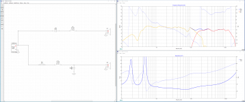
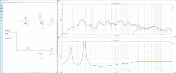
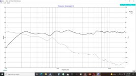
I am using the MLTL-10 speakers (as I am calling them) some more with the active crossover, and then I will measure them again - I am hoping that the impedance bumps in the woofer (at 700-850Hz in particular, but also just above 100Hz) will diminish somewhat. But even with the current measurements, I like this crossover a lot - it is much more even, with what I consider a good tonal balance:
Should I be concerned with the two impedance peaks in the woofer? I think a resistor to ground can lower these?
Should I be concerned with the two impedance peaks in the woofer? I think a resistor to ground can lower these?
Attachments
Last edited:
Impedance bumps tend to indicate a resonance. They might only be a problem if there is a noticeable peak in the response. The upper ones may be related to the construction of the woofer and the lower one may be due to a box resonance.
A crossover can interact with them to make a response bump more or less of a problem, so this is what to look out for. However, until you can take smooth measurements things like this are going to remain unclear.
A crossover can interact with them to make a response bump more or less of a problem, so this is what to look out for. However, until you can take smooth measurements things like this are going to remain unclear.
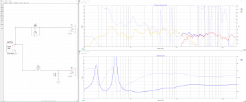
Okay, things are looking better - I took new measurements, both the ZMA and the FRD. The former were essentially unchanged, but the latter were quite different, as I took them for both drivers with the mic in the same location about 3' away on the listening axis. And the crossover is simpler - 1st order on the tweeter (basically to prevent low frequencies from hitting the tweeter) and 2nd order on the woofer. Three parts for the basic components, with a fourth being a bypass cap on the tweeter.
I also measured the drivers with the digital active crossover, as well as the speaker system, and this was helpful as a guide for balancing the response in XSim. The acoustic crossover point is ~1.7kHz.
Edit: I was visually comparing these - and then I realized I could import the FRD of the speaker into XSim, and the digital XO is rolling off the tweeter more, so I will look at adding a coil or resistor on the tweeter to adjust it. See the second image, and the green trace.
I will be ordering Audyn A4 33uF caps, and the 1.6mH inductor will be ERSE. I will get Sonicap 0.1uF for the bypass.
Attachments
Last edited:
I will add a 6 ohm 12W Mills resistor on the tweeter, to bring the tweeter down to just a *touch* louder than it is with the digital XO. I will order a 7 ohm, for our friend Justin Case. These will work for up to about 40W at the amp which is at least 100dB and about 10W heat dissipation from the resistor.
Question: in XSim on the coil tuning, there is an ESR setting - what is this, and do I need to set it to a value for the actual coil that I want to buy? The default is 350 milliohms.
Question: in XSim on the coil tuning, there is an ESR setting - what is this, and do I need to set it to a value for the actual coil that I want to buy? The default is 350 milliohms.
Yes, every coil has a resistance.
It should also be taken into account when simulating or buying coils.
A trick to know if the phase behaviour at xo point is OK:
wire the tweeter reversed, the spl measurements should show a deep drop at that xo point.
It should also be taken into account when simulating or buying coils.
A trick to know if the phase behaviour at xo point is OK:
wire the tweeter reversed, the spl measurements should show a deep drop at that xo point.
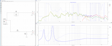
Hi Allen, the ERSE 14ga coil has a DCR rating of 0.278 ohm - is that the value to use in the ESR? If so, it makes a small change. Here's what I am going to go with - the gray trace is the speaker system with the digital XO that I measured from the exact same mic position as the driver FRD measurements.
Thanks Danny, I just checked and it looks good and proper.
I think that possibly the reason the tweeter level looks low, is that it is a dipole? So, in the room, there is 2X the energy, maybe?
These are *really* close so I am going to go ahead and order the parts - my very first analog crossover! Woo hoo!
Attachments
Last edited:
I realized that the impedance above 1kHz could be improved with an L-pad - luckily a second 6 ohm in parallel with the first, and a 10 ohm to ground drops the impedance to essentially the same as the tweeter itself; about 7.5 ohms.
Minimum impedance is ~3.6 ohms at ~150Hz, and between about 110Hz - 230Hz is below 4 ohms. I am not sure, but does this look like the nominal impedance is about 5 ohms, or maybe 6 ohms?
Minimum impedance is ~3.6 ohms at ~150Hz, and between about 110Hz - 230Hz is below 4 ohms. I am not sure, but does this look like the nominal impedance is about 5 ohms, or maybe 6 ohms?
Attachments
I have a question Neil, how do they come together in the direct sound versus the ambient?
The reason I ask is because at low frequencies your bass is going to ignore the cabinet because of the large wavelengths. It will have wide directivity. The mids will project forward on the baffle. The highs once again go wide with the dipole. Do you notice the ambient sound being harsh or disjointed?
The reason I ask is because at low frequencies your bass is going to ignore the cabinet because of the large wavelengths. It will have wide directivity. The mids will project forward on the baffle. The highs once again go wide with the dipole. Do you notice the ambient sound being harsh or disjointed?
Thanks, I will think of these as 4 ohm speakers - which makes sense, since the woofers are 4 ohms nominal.
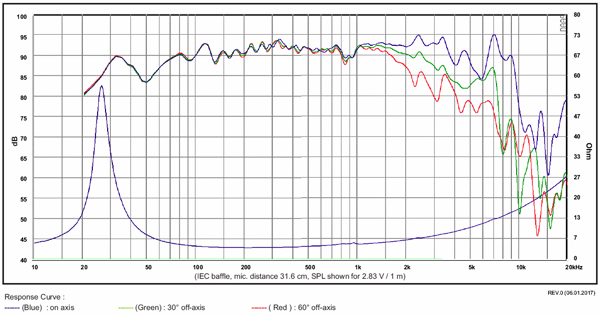
As far as the directionality goes - these speakers are anything but harsh or disjointed. The tweeter is 10dB down at roughly 1500Hz, and going by the published response of the woofer (as with any 8" driver) they only start to get narrower at just above 1000Hz, and by 1500Hz is about 6dB down at 60 degrees off axis. So the drivers are summing in that range.
The dispersion of the highs is part of why this speaker sounds so good, and why they essentially disappear, most of the time.
I will try to take some on axis and off axis measurements.
The baffle is only 10.5" wide - barely an 1" wider than the outer frame diameter, and only a bit more at the top. So only the baffle below the woofer is the majority of what is "supporting" the midrange.
Last edited:
Please Evaluate Proposed Crossover
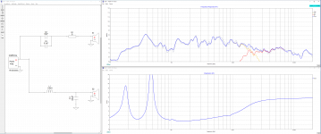
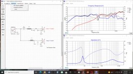
Designing a new crossover for a low powered (20W/Ch) Amazon bluetooth setup model R28BTUS. First graphic is stock 1” 8 ohm tweeter w/ 2.2uF cap and 4” 4 ohm woofer running free. Second graphic is the same speaker with the Dayton ND-20TA-6 and proposed revised crossover. Third graphic is the same, but showing only total response for clarity. XSim dxo file seems to large to upload.
Would appreciate a “sanity check” and any comments/thoughts on my proposed crossover.
Attachments
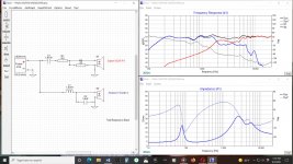
I am far from an expert, but the 1-2kHz region seems to be a bit higher than ideal. Maybe a different (lower?) cap value on the tweeter would roll it off a bit more / higher up to reduce the summed response through there?
Also, maybe adjust the R2 value to lower the impedance of the tweeter and/or adjust the C2 value to roll the woofer off a bit quicker? The overlap region seems wider than what I would think is ideal.
Also, maybe adjust the R2 value to lower the impedance of the tweeter and/or adjust the C2 value to roll the woofer off a bit quicker? The overlap region seems wider than what I would think is ideal.
Last edited:
- Home
- Loudspeakers
- Multi-Way
- Introduction to designing crossovers without measurement