Example screenprint attached.
Kind regards,
David
Thanks! I have been looking for this for a while now.
Last edited:
Thanks! I have been looking for this a while now.
If I were to change the size of this horn, what paramenters do I have to change to still have a JMLC profile?
I noticed I don't have the Lec option. Time to upgrade Hornresp!
Edit: It didn't work. Lec is still not there. I have v. 34.80.
Hi Rewind,
1. Make a copy of the default record.
2. Highlight the Con input box.
3. Press the L key.
4. Double-click the S2 input box.
Then go from there.
Kind regards,
David
EDIT 1 - I replied before you posted your Edit2
") .
.EDIT 2 - Now it seems you have deleted most of your original message
.
Last edited:
Hello WHG,
Images attached is a comparison between JMLC's spreadsheet (red) and my method (blue) with same condition.
Best regards,
Hsieh W M
Are you comparing your method with JMLC's "Old Calculaton" or "New Calculation"?
Your method appears to more similar with the "New Calculation". Correct me if I'm wrong, but doesn't Horn Response use JMLC's "New Calculation"?
Exact JMLC VBA Code
Hi David,
Thanks for the response. Any changes to the code since Message #1159 ?
Regards,
Bill
Hi Bill,
I haven't checked the code to see if the calculations are identical, but the results appear to be very close to those produced by the "exact method" documented in my Post #1139 and subsequent related messages. Hornresp has the option of exporting data using either the "exact method" or Jean-Michel's 2007 spreadsheet method. The Hornresp "exact method" is extremely accurate.
Kind regards,
David
Hi David,
Thanks for the response. Any changes to the code since Message #1159 ?
Regards,
Bill
Last edited:
Edit3: Hornresp support is too quick. I figured it out by myself.
Another question. When designing JMLC round horns for compression drivers that are able to reach 330Hz, what is a reasonable electrical impedance, and acoustic impedance, and group delay, etc. What is there to look out for?
I know that the impedance for the TAD TD-2001 can be problematic below 600Hz. But there are others like Yamaha JA6681B that can do a better job at 330Hz.
If I got it right, e.g. a 1st order capacitor would have trouble because depending on the frequency in the music it would highpass at different points.
If above statement is true, is there anything to do about it? Maybe an autotransformer could help. I have read that an autotransformer can lower the impedance. Here JMMLC and David Slagle are debating autoformers vs l-pads.
High Efficiency Speaker Asylum
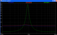
"Did a quick simulated impedance curve and the autoformer and Lpad were very similar loads to the crossover network. Green is the load impedance of my simulated "speaker" and blue is a 12dB pad and green is a 12dB autoformer with damping resistor.
another interesting thing with the autoformers is you can do the crossover network at higher impedances making the cap values smaller. "
- David Slagle
"Hello,
There is not always a need to have a very low impedance source to drive compression, drivers.
With excellent drivers like the TD2001 a high series impedance is beneficial.
Either a linearization of the frequency response cruve can be acheived and a reduction of distortion (as predicted by Mills and Hawksfod).
see my measuremenst of a TAD TD2001 compression driver mounted on a Le Cléach horn (with high pass) in the following link.
Best regards
TD2001 current driven (left) and voltage driven (right)"
- JMMLC
Although in the last example, JMMLC highpassed it much higher than 330hz, so impedance was hardly a problem.
I figured it out by myself.Another question. When designing JMLC round horns for compression drivers that are able to reach 330Hz, what is a reasonable electrical impedance, and acoustic impedance, and group delay, etc. What is there to look out for?
I know that the impedance for the TAD TD-2001 can be problematic below 600Hz. But there are others like Yamaha JA6681B that can do a better job at 330Hz.
If I got it right, e.g. a 1st order capacitor would have trouble because depending on the frequency in the music it would highpass at different points.
If above statement is true, is there anything to do about it? Maybe an autotransformer could help. I have read that an autotransformer can lower the impedance. Here JMMLC and David Slagle are debating autoformers vs l-pads.
High Efficiency Speaker Asylum
"Did a quick simulated impedance curve and the autoformer and Lpad were very similar loads to the crossover network. Green is the load impedance of my simulated "speaker" and blue is a 12dB pad and green is a 12dB autoformer with damping resistor.
another interesting thing with the autoformers is you can do the crossover network at higher impedances making the cap values smaller. "
- David Slagle
"Hello,
There is not always a need to have a very low impedance source to drive compression, drivers.
With excellent drivers like the TD2001 a high series impedance is beneficial.
Either a linearization of the frequency response cruve can be acheived and a reduction of distortion (as predicted by Mills and Hawksfod).
see my measuremenst of a TAD TD2001 compression driver mounted on a Le Cléach horn (with high pass) in the following link.
Best regards
TD2001 current driven (left) and voltage driven (right)"
- JMMLC
Although in the last example, JMMLC highpassed it much higher than 330hz, so impedance was hardly a problem.
Attachments
Last edited:
Any changes to the code since Message #1159 ?
Hi Bill,
No changes.
Kind regards,
David
Last edited:
Hi pooge,
The method is being compared against Jean-Michel's "New Calculation", as documented in his 2007 spreadsheet. The "Old Calculation" was documented in his January 2000 spreadsheet.
As mentioned in Post #1756, Hornresp has the option of exporting data using either the Hornresp "exact method" or Jean-Michel's 2007 spreadsheet ("New Calculation") method.
Kind regards,
David
Are you comparing your method with JMLC's "Old Calculation" or "New Calculation"?
The method is being compared against Jean-Michel's "New Calculation", as documented in his 2007 spreadsheet. The "Old Calculation" was documented in his January 2000 spreadsheet.
Correct me if I'm wrong, but doesn't Horn Response use JMLC's "New Calculation"?
As mentioned in Post #1756, Hornresp has the option of exporting data using either the Hornresp "exact method" or Jean-Michel's 2007 spreadsheet ("New Calculation") method.
Kind regards,
David
Hi again,
Bit sooner than promised - I ported code to matlab (almost nothing too it really) and got the attached output.
Looks reasonable to me! It took quite some time to run but I assume that's because of your more refined calculations.
It will take me quite a bit longer to go through the mathematics and understand the code, but all good so far.
Look forward to hearing how the elliptical calculation works; do you basically repeat the circular calculation multiple times for different parameters?
Thanks again, great stuff!
Hi cv,
Here is the second module for calculating a horn.
Firstly, use the module 'cal_Le_Cleach_horn_template.txt' with
f0=320;
a=0.0254/2;
T=1/sqrt(2);
run a template profile, and save it as data file
save('Cleach_horn_template_f0_320_a_0254_T_1_sqrt_2.dat',theta,d,h,Lt)
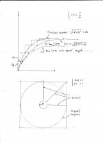
Stretching (or compressing) the template curve along x axis,
and then make the new curve has same total length as template curve.
We will get a new curve with same total length but different x axis length.
By the bisection method (same as used in first module),
we will get a set of curve that meet x axis length command 'xtr'.
The set of curve make up the square horn initial profile.
nth=360;
There are 360 curves composing the horn profile.
We only have to generate 91 different curves.
nd=96;
A fixed length L, equals the length from throat to 90 degree (max y) divided by nd,
is used to do piecewise linearization on each curve,
The initial profile will not meet the expansion rate we need.
The data is saved as a temporary file
save('cal_Le_Cleach_horn2.dat',nd,th_n,rs,L)
for next step calculating.
Best regards,
Hsieh W.M.
Attachments
How does it compare with that produced by DJM's Horn Loudspeaker Response Analysis Program [1]?
Hi Bill,
Further to my earlier message, I have now had a look at the code. While some of the formulas are expressed differently, the method is identical to that used in the Hornresp "exact" model, and produces precisely the same results.
Kind regards,
David
Dear WM,
Thanks very much again! I've only had time for a quick look but am sure things will be clearer when I get a chance to play with the code later this week.
Best,
cv
Hi CV,
Thanks for your reply.
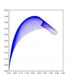
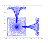
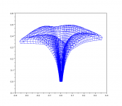
Here is the last part for a square horn.
Having got the temporary data file 'cal_Le_Cleach_horn2.dat'
from previous step, running this last module,
we will get a square horn as images attached.
I usually save the result as a data file for subsequent processing.
save('320Hz square horn_kc_1_final.dat',nth,d,h,phi,b0,i)
The method in this module is adjusting the expansion theta,
step by step from throat to mouth, according to the horn equation.
At(i)=Ah*(cosh(x/x0)+T*sinh(x/x0))^2;
The expansion theta in each direction is adjusted by the same ratio
from its initial value.
th_n(i,n)=th_nd(i,n)*(1+sD/10);
where sD is index of bisection method.
But there is a problem in this module.
The "wavefront surface" calculation formula used in first module
is not applicable in this module. Because the surface is not round.
I can not find a new method to calculate this surface.
I just change the coefficient from "2*%pi" to "2*%pi/nth".
That is, use "piecewise round surface" to represent the real surface.
s(i)=s(i)+2*%pi/nth*(d(i,n)*b(i)*th_n(i,n) + b(i)^2*(cos(th_a)-cos(th_b)));
I don't know whether this is a good approximation or not.
I had run a same horn with nth=360 and nth=3600 respectively,
There are only little differences around mouth.
Best regards,
Hsieh W.M.
Attachments
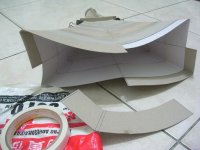
I call it rectangular JMLC horn.
It is calculated by JMLC wave-front expansion method, but with different expansion rate in each direction.
fc 1kHz, 1 inch throat, T=1/sqrt(2).
Sample is made by cardboard, and reinforced by wall putty.
Hi Hsiehwm
Great build
Am looking myself for a build for TAD2001 with rectangular jmlc, for same reason as you state (proximity listening round 3m). I aim a cutoff of say 290-300 to use properly the 2001.
Would you publish your way of building, maybe in another thread ?
BR from Paris
Jean-Louis
What is the Acoustical Advantage...
of a square section horn over that of one with a circular section?
If we wish to change the aspect ratio of the radiating pattern, then pursuit of a horn that implements section transformation from circular at the throat to elliptical throughout the remaining extent of the horn body, may be more productive strategy. Here the aspect ratio at the throat, Xt/Yt =1 is transformed to Xm/Ym = Km (Km>1) at the mouth. Note that the center element remains circular, but the ring elements do not.
Each of these elements may be represented by a patch (Coon's) [1] bounded by a combination of elliptical and circular arc segments. Note that the iterative calculation of the areas is now approaching that of a compute bound problem.
Regards,
WHG
[1] Patch Reference
http://www.engr.sjsu.edu/ragarwal/ME165/ME165_Lecture_Notes_files/Chapter_5_SURFACES.pdf
Hi CV,
>snip<
The method in this module is adjusting the expansion theta,
step by step from throat to mouth, according to the horn equation.
At(i)=Ah*(cosh(x/x0)+T*sinh(x/x0))^2;
The expansion theta in each direction is adjusted by the same ratio
from its initial value.
th_n(i,n)=th_nd(i,n)*(1+sD/10);
where sD is index of bisection method.
But there is a problem in this module.
The "wavefront surface" calculation formula used in first module
is not applicable in this module. Because the surface is not round.
I can not find a new method to calculate this surface.
I just change the coefficient from "2*%pi" to "2*%pi/nth".
That is, use "piecewise round surface" to represent the real surface.
s(i)=s(i)+2*%pi/nth*(d(i,n)*b(i)*th_n(i,n) + b(i)^2*(cos(th_a)-cos(th_b)));
I don't know whether this is a good approximation or not.
I had run a same horn with nth=360 and nth=3600 respectively,
There are only little differences around mouth.
Best regards,
Hsieh W.M.
of a square section horn over that of one with a circular section?
If we wish to change the aspect ratio of the radiating pattern, then pursuit of a horn that implements section transformation from circular at the throat to elliptical throughout the remaining extent of the horn body, may be more productive strategy. Here the aspect ratio at the throat, Xt/Yt =1 is transformed to Xm/Ym = Km (Km>1) at the mouth. Note that the center element remains circular, but the ring elements do not.
Each of these elements may be represented by a patch (Coon's) [1] bounded by a combination of elliptical and circular arc segments. Note that the iterative calculation of the areas is now approaching that of a compute bound problem.
Regards,
WHG
[1] Patch Reference
http://www.engr.sjsu.edu/ragarwal/ME165/ME165_Lecture_Notes_files/Chapter_5_SURFACES.pdf
Last edited:
Sidebar
The recommended minimum crossover frequency for the TD2001 is 800Hz @ 12dB/oct.
For this driver operated as recommended by TAD, a horn with a [Fc] of about 400 should be sufficient.
If a lower c/o frequency is required, then use the TD4001 instead with the horn design you are anticipating.
Regards,
WHG
Hi Hsiehwm
Great build
Am looking myself for a build for TAD2001 with rectangular jmlc, for same reason as you state (proximity listening round 3m). I aim a cutoff of say 290-300 to use properly the 2001.
Would you publish your way of building, maybe in another thread ?
BR from Paris
Jean-Louis
Hi Jean-Louis,
The constructing steps are very simple.
A round horn can be approximated by a set of conical segments.
A JMLC type horn, with equal wall length at every direction,
can be decomposed to small pieces like a round horn.
I write a procedure to do this, and print it out by a CAD tool.
Constructing begins from throat. Stick the small pieces by twin-adhesive,
two layers overlapped, and glue the gap between pieces.
But I don't think this is a good method for a large horn.
Without any mold or scaffold, it is difficult to construct precisely.
And vibration will be a big problem, especially at throat.
Best regards,
Hsieh W.M.
Attachments
of a square section horn over that of one with a circular section?
If we wish to change the aspect ratio of the radiating pattern, then pursuit of a horn that implements section transformation from circular at the throat to elliptical throughout the remaining extent of the horn body, may be more productive strategy. Here the aspect ratio at the throat, Xt/Yt =1 is transformed to Xm/Ym = Km (Km>1) at the mouth. Note that the center element remains circular, but the ring elements do not.
Each of these elements may be represented by a patch (Coon's) [1] bounded by a combination of elliptical and circular arc segments. Note that the iterative calculation of the areas is now approaching that of a compute bound problem.
Regards,
WHG
[1] Patch Reference
http://www.engr.sjsu.edu/ragarwal/ME165/ME165_Lecture_Notes_files/Chapter_5_SURFACES.pdf
Hello WHG,
Thanks for the message been provided.
The approach you mentioned is just like JMLC's IWATA horn.
But the shape transformation is applied on "pseudo wavefront surface".
If we change it to horn shape, the approach will not work.
And this approach can not derive a horn shape like JMLC's E-horn.
In E-horn, the expansion angle reaches 90 degrees simultaneously in each directions.
Best regards,
Hsieh W.M.
Simultaneous = Same Time of Arrival
Over a square horn mouth boundary lying in the [x,y] plane, the isophase wave surface does not arrive at the same time over the entire horn perimeter. The most delayed arrival will be at the corners. So the notion of simultaneity does not apply here unless the mouth is made to terminate in a curvilinear isophase surface as well.
Of necessity, in respect to the horn z axis, the horn body recedes sooner in the [x,z] plane than [y,z] plane for the elliptical section horn. And in cutting planes between these limits, such recession will be graduated. For the square section horn, recession is greatest at 45 deg. cutting planes through the corners.
While I am interested in using JMLC's method, I am not necessarily interested in replicating his specific designs.
I still fail to see an acoustic benefit to be derived by the magnitude greater effort required to generate a square section horn to replace one of round section.
Regards,
WHG
Hello WHG,
Thanks for the message been provided.
The approach you mentioned is just like JMLC's IWATA horn.
But the shape transformation is applied on "pseudo wavefront surface".
If we change it to horn shape, the approach will not work.
And this approach can not derive a horn shape like JMLC's E-horn.
In E-horn, the expansion angle reaches 90 degrees simultaneously in each directions.
Best regards,
Hsieh W.M.
Over a square horn mouth boundary lying in the [x,y] plane, the isophase wave surface does not arrive at the same time over the entire horn perimeter. The most delayed arrival will be at the corners. So the notion of simultaneity does not apply here unless the mouth is made to terminate in a curvilinear isophase surface as well.
Of necessity, in respect to the horn z axis, the horn body recedes sooner in the [x,z] plane than [y,z] plane for the elliptical section horn. And in cutting planes between these limits, such recession will be graduated. For the square section horn, recession is greatest at 45 deg. cutting planes through the corners.
While I am interested in using JMLC's method, I am not necessarily interested in replicating his specific designs.
I still fail to see an acoustic benefit to be derived by the magnitude greater effort required to generate a square section horn to replace one of round section.
Regards,
WHG
T <constant>
T is constant, for the area expansion projected over a presumed curvilinear isophase wave front surface. What changes between the throat and mouth is the ratio of [x] and [y] coordinates for a [z] axis horn; e.g. [xt] = [yt] (at the throat) to [xm] = f(ø,z)*[ym] (at the mouth) where [f(ø,z,)] is some function of [ø] and [z]. To define the horn body, coordinates lying on cutting planes through the z axis at [ø] angles other than [0] or [90] degrees must be determined as well. Fortunately only one quadrant in the [x,y] plane is needed, as the others are mirror images.
Regards,
WHG
Do you remember how eJMLC was constructed? - T parameters varies from-to? Linearly or non-linearly? I've never seen original spreadsheet. Maybe JMLC once explained?
T is constant, for the area expansion projected over a presumed curvilinear isophase wave front surface. What changes between the throat and mouth is the ratio of [x] and [y] coordinates for a [z] axis horn; e.g. [xt] = [yt] (at the throat) to [xm] = f(ø,z)*[ym] (at the mouth) where [f(ø,z,)] is some function of [ø] and [z]. To define the horn body, coordinates lying on cutting planes through the z axis at [ø] angles other than [0] or [90] degrees must be determined as well. Fortunately only one quadrant in the [x,y] plane is needed, as the others are mirror images.
Regards,
WHG
Anyone have an idea of how to do the Iwata JMLC horn?
I would like to make a horn like these guys:
Pavillons JMLC/Iwata 220, ça sonne ... - Le blog de audiobricolos
I have access to cnc machinery and I'm well versed in NURBS modelling and woodwork it's just a matter of getting the 3d model sorted out.
I would like to make a horn like these guys:
Pavillons JMLC/Iwata 220, ça sonne ... - Le blog de audiobricolos
I have access to cnc machinery and I'm well versed in NURBS modelling and woodwork it's just a matter of getting the 3d model sorted out.
- Home
- Loudspeakers
- Multi-Way
- Jean Michel on LeCleac'h horns