There are a few others Lynn, I had a long list of candidates once from James D who you may know and whose judgement I trust.
The others I can suggest are the SME 3012 II and the 3012 I ( heavier, better ) both a bit pricey on Ebay these days, but likely better than either of these is Thomas Schick's arm -
Schick tonearm
Which I have had rave reviews on, from another correspondent who has an all-valve system and used to use the Mk. 1 3012 . You may have seen his prototype at ETF in 2004 or 2005 . Ok, it's about E900 so not cheap ...
Well, PM me if you want to keep the long list of candidates off the forum, otherwise I think we'd all like to know. Tonearms are very subjective animals, with so many differences attributable to near-invisible differences in construction, and the arcane stick-slip behavior of bearings as the arm wobbles back and forth from small record warps.
Ha ha !
I'm not trying to keep it secret, just need to dig out the actual message from thousands I have from James. Unfortunately I've just finished work for about 10 days hol, and I think that message was on my work e-mail , ooops . I WILL get back to you on this, but bear in mind some of the ones he rated highest were well-known ( expensive) favourites like the 1st-model SME 3102 , and the Fidelty Research FR-64 . This info was applicable to all the low-compliance cartridges like 103,103R , SPU, EMT ( various) as I know James only rates these types. For the 103R ( not the SPU ) there is one unlikely winner which is the rather insubstantial-looking Mayware formula IV unipivot, which can be made to work very well if the headshell is loaded-up with 5-10g of lead ( shim ) . The midrange and treble are glorious , with that beautiful fluidity you get from unipivots.
Oh, yes, a longer , heavier unipivot would be the ultimate, and James's very favourite I believe is the top-model Morsiani arm from Italy .
Ha ha !
I'm not trying to keep it secret, just need to dig out the actual message from thousands I have from James. Unfortunately I've just finished work for about 10 days hol, and I think that message was on my work e-mail , ooops . I WILL get back to you on this, but bear in mind some of the ones he rated highest were well-known ( expensive) favourites like the 1st-model SME 3102 , and the Fidelty Research FR-64 . This info was applicable to all the low-compliance cartridges like 103,103R , SPU, EMT ( various) as I know James only rates these types. For the 103R ( not the SPU ) there is one unlikely winner which is the rather insubstantial-looking Mayware formula IV unipivot, which can be made to work very well if the headshell is loaded-up with 5-10g of lead ( shim ) . The midrange and treble are glorious , with that beautiful fluidity you get from unipivots.
Oh, yes, a longer , heavier unipivot would be the ultimate, and James's very favourite I believe is the top-model Morsiani arm from Italy .
With this kind of cartridges (103, SPU, Koetsu, AT33, EMT), stiff ones (not reallt the EMT... but), the Fidelity Research FR66S will probably be a very good, stable and versatile choice... The problems are that you will need a large enough turntable to install it, the turntable has to be very heavy, you'll never be able to use a high compliance cartridge, and it is not cheap.... But if you use a stiff cartridge (and play a little bit with the headshell), what a pleasure (and easy to trim with the B60 base).
Andre
Attachments
Last edited:
The Well Tempered is very good at a sane price, well thought if a bit out of the box.
Well Tempered Lab - Amadeus
Well Tempered Lab - Amadeus
Thanks, Island Pink, for the Shick link. The bearing discussion is very interesting - I feel the bearings are at the heart of what a tonearm does, since they are the most uncertain element of the mechanical linkage between the turntable structure and assorted mechanical noises created by the cartridge (what is sometimes called "needle talk").
Since the cartridge noises are highly resonant in character, the effect they have on the bearing is very important. One school of arm design uses a lossy (typically wood) arm shaft, while the more common approach uses metal cylinders (which are very efficient at transmitting cartridge noises into the bearing assembly).
This is akin to the mechanical path between the driver frame and where the floor meets the loudspeaker enclosure. There's one school that believes in decoupled driver frames (flexible mounts, etc.), and the other, a rigid path from frame to floor. The Ariel is example of the second school, with the rigid front panel coupled to the floor, and internal elements in the enclosure that go from front panel to floor.
Perhaps a more useful model is the mechanical impedance (versus frequency) that the cartridge (or speaker driver) sees looking into the headshell or armtube. Resonances in the armtube (or speaker enclosure) represent narrowband shifts in this impedance, and mechanical coupling elements that generate noise (like bearings) are a secondary distortion and noise source.
Although a lossy bearing (like a wire under tension) is intellectually appealing (low bearing noise), the string goes into its own set of harmonics, and represents a dead-end for the mechanical energy coupled into the armwand. It's a good question what happens with a unipivot - lower bearing noise, of course, but the mechanical path to ground is questionable, as well as uncertain azimuth as record warps are traversed. (Record warps on even the smoothest discs is always far larger than groove modulations.) Another question is how lateral (center image) energy is handled differently than vertical (out-of-phase) energy; the differences in mechanical impedance (as seen from the cartridge) will affect the spatial properties of the soundfield.
There are similar and interesting challenges for loudspeaker design. Aside from the desired conversion of current into mechanical back-and-forth motion in the voice coil and former, there is magnetic flux variation that is reflected into the ceramic, Alnico, neodymium, or field-coil magnet (which have some degree of compliance and acts as a nonlinear load), and the mechanical reaction forces that appear on the driver frame. Neither is that easy to measure, but are quite real and affect the sound. Even the simple strategy of trying different flat platforms under a loudspeaker (made from metal, wood, MDF, glass, marble, slate, etc.) reveals surprisingly large subjective differences. Small changes to the magnetic structure of a loudspeaker are also quite audible, although not immediately obvious on THD curves.
The fact that any difference is audible reveals just how significant these stray mechanical energies are. The same applies to the digital domain; that any difference is audible between various jitter-reduction schemes (cables, asynchronous reclocking, FIFO buffers, low phase-noise clocks, etc.) indicates that a seemingly minor parameter is actually quite important in subjective terms.
These weird little "problems" - from the viewpoint of mainstream designers - are a powerful insight into secondary "side-effects" where the physical device departs from the standard textbook model, and are quite illuminating in pointing the way forward for more research. If a seemingly small change, that does not seem to affect the standard model, yet results in a large subjective change, that's a good direction to look for improving the measurement system so it better matches what is heard.
Last edited:
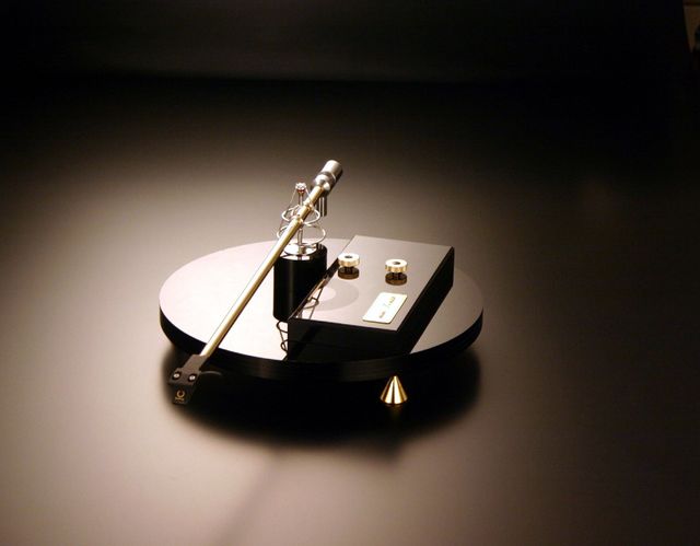
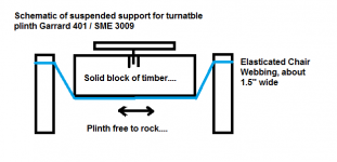
I'll just throw in what I thought was one of the neatest solutions to isolating a turntable plinth I ever saw, can't remember who made it...")
The SME arm and Garrard 401 turntable was mounted on a solid wooden plinth, but the whole thing was suspended on two straps of elasticated furniture webbing within a rectangular wooden frame. You had to see this thing rocking gently backward and forward while tracking securely to believe. Best mounted on a solid wall of course. Looked a bit like the old SME plinth, but NO SPRINGS.
The acoustic isolation from vibration was quite superb. Your engineering problem reduces to simply the plinth, turntable and arm mounting as a closed system.
Attachments
The decoupled/damped versus rigid/undamped debate is an interesting one whether in loudspeakers or record players.
I think the verdict is you go for rigid construction as a first design goal to get resolution, and then apply a path to dissipate energy in the right place. SME are willing to discuss their turnaround on fostering light floppy construction for high-compliance magnetic cartridges in the seventies, back to the sort of heavier arms with tensioned bearings suitable for better low-compliance moving-coil cartridges.
SME - Series V
You don't have to read it all, but they wanted to get plinth support resonances around 2 Hz and arm resonances nicely separated around 8 Hz, with signal above 20 Hz. Damping is then lastly applied to an optimum undamped solution. Makes sense.
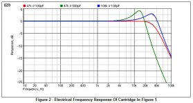
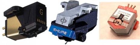
I have previously mentioned how useless most magnetic cartridges are. The high inductance Shure designs ended up with a second-order high frequency LC response that had the stylus moving at 180 degrees to the groove as in the Rod Elliott plot at high Q. It wouldn't matter with a microphone, but for a cartridge that means mistracking.
Magnetic Phono Pickup Cartridges
By contrast, designs like the Grado and venerable 1960's Decca London worked at first-order high frequency, so were much sweeter sounding, albeit they need a heavier tonearm to avoid overexciting arm resonance.
That's a long post by my standards, sorry. Seems to me you get it all rigid, but then think about how to dissipate the energy with one fell swoop. Maybe sandwich construction is a viable solution. Glue a piece of granite to a piece of wood in your plinth, and the energy can dissipate. Many ways to skin a cat. It's all physics in the end.
I think the verdict is you go for rigid construction as a first design goal to get resolution, and then apply a path to dissipate energy in the right place. SME are willing to discuss their turnaround on fostering light floppy construction for high-compliance magnetic cartridges in the seventies, back to the sort of heavier arms with tensioned bearings suitable for better low-compliance moving-coil cartridges.
SME - Series V
You don't have to read it all, but they wanted to get plinth support resonances around 2 Hz and arm resonances nicely separated around 8 Hz, with signal above 20 Hz. Damping is then lastly applied to an optimum undamped solution. Makes sense.
I have previously mentioned how useless most magnetic cartridges are. The high inductance Shure designs ended up with a second-order high frequency LC response that had the stylus moving at 180 degrees to the groove as in the Rod Elliott plot at high Q. It wouldn't matter with a microphone, but for a cartridge that means mistracking.
Magnetic Phono Pickup Cartridges
By contrast, designs like the Grado and venerable 1960's Decca London worked at first-order high frequency, so were much sweeter sounding, albeit they need a heavier tonearm to avoid overexciting arm resonance.
That's a long post by my standards, sorry. Seems to me you get it all rigid, but then think about how to dissipate the energy with one fell swoop. Maybe sandwich construction is a viable solution. Glue a piece of granite to a piece of wood in your plinth, and the energy can dissipate. Many ways to skin a cat. It's all physics in the end.
Attachments
Now that I've been looking more deeply into the speed-stability issue, there are some very strange problems with suspended TT's with a motor rigidly attached to the non-moving base/plinth.
Most TT suspensions have a very high Q - in other words, they take a long time to settle from an initial shock, like a car with worn-out shock absorbers (dampers). Anyone that's ridden in a car like this will quickly feel seasick from the constant wallowing motion, since road shocks continually re-excite the high-Q 2nd-order lowpass filter (springs and mass of car). One little trick that car manufacturers learned in the early Sixties were staggered spring rates for front and back, with about a 15% difference in spring rates, so the system as a whole would settle more quickly, and not be as prone to go into nauseating front-to-back rocking motions. Cars made in the 1950's with American-soft suspension were notorious for sickening the passengers - I remember this all too well from my own youth. I still prefer firm suspensions, partly for that reason.
I've noticed that suspended TT's with either 3 or 4 springs can take an amazingly long time to settle from a single shock - sometimes as long as a minute, which implies a very high Q in the range of 20 to 100. This is just poor design; in real-world environments, the TT will always be in motion, unsettling the tracking force on the tonearm and having a very complex effect on the gyroscopic momentum of the platter. Give the system a good shove while the platter is turning, and watch the initial lateral motion turn into high-order rocking modes, as momentum is transferred from one spring to another. (Asymmetric distribution of mass will result in simple lateral shocks gradually growing into much more complex rocking and rotary motions - they'll get smaller, but there are many more of them, moving in more dimensions.) When the TT finally settles, you'll notice the final motions have no relationship at all to the original shock.
It gets much worse if the motor is stationary while the platter moves around; that changes belt tension (never a good thing), as well as the effective location of the motor (relative to the platter). In other words, the power fed into the belt will shift as the platter moves around, and the power surges stored in the compliance of the belt will then independently excite the spring suspension and keep them in motion.
A motor that is not part of floating suspension is going to have a very poorly defined lowpass filter between the motor and platter. If the platter is free to move laterally - and with springs, it will be - it will surge back and forth if environmental shocks get the springs moving, which leads to uneven power delivery, as well as a high-Q lowpass filter that actually stores energy, instead of filtering it out.
High-order (2nd-order and above) filters that have dynamic elements introduce a lot of problems. One example are MM cartridges where the cartridge inductance and phono-cable capacitance form a 2nd-order lowpass filter in the 14 to 22 kHz range. This seems innocent enough until you realize that both the inductance and cable capacitance are low-quality LC elements, nothing like the sort of thing you'd use in the RIAA section of a phono preamp, so the lowpass filter is not well defined under dynamic conditions, and introduces significant time-domain distortions of its own.
If you must use a high-inductance cartridge (typically these require a stated cable capacitance to measure flat), better to use as little capacitance as possible, and HF equalize in the preamp at a location that is electrically isolated from the input circuit. That way, you can hear the cartridge by itself, instead of a resonant 2nd-order lowpass filter with a bad capacitor (even astronomically expensive cables make pretty bad capacitors).
In loudspeakers, most of the reason I use Zobel inductance-cancelling RC networks is to isolate the low-quality VC inductance from the crossover network. I go to a lot of trouble to build the crossover from the highest-quality parts I can find, and I don't want them dancing a tango (forming a filter function) with the really low-quality VC inductance, which is a dynamic, program-controlled inductance with high-order nonlinearities (compared to an air-core inductor).
To return to the original premise, one of the things to avoid in audio design is transforming a simple problem into a more complex high-order one (that might measure better but not sound better). In amplifiers, if the loop feedback or power-supply regulation is disturbed by transient current surges, the performance of the amplifier can greatly degrade while the loop is stabilizing itself. In extreme cases, if the loop cannot return to stability, the amplifier will be destroyed, and possibly take out the speaker as well. In milder cases, the loop might take a long time to settle, and go through chaotic modes as it does so (chaotic modes are fairly common in complex feedback circuits, especially those with nonlinear elements).
Loudspeakers typically have lower-order behavior than amplifiers (lacking a power source, they can't oscillate), but high-order modes in the cabinets need to be chased out, and crossover networks need to be examined to see if they behave differently with different amplifier source impedances and also examined to see if nonlinear terms in the driver are interacting with the network.
It's not immediately obvious, but if you suspended a direct-drive TT, the feedback correction loop might take longer to settle, which is not a good thing. This is easy enough to examine by giving the TT a good shove and seeing how long it takes the servo-correction error signal to settle to zero.
Last edited:
Quoted because of page turn...LOL
In studying series crossovers with a lot of confidential information supplied by my friend speakerman19422, I have come to realise that you must work with voice coil inductance for a good result, not just try and equalise it.
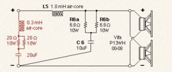
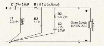
Look at this classic radio-frequency solution to a 2500Hz butterworth:
The 4 ohm resistance is the RL bafflestep circuit. Now all you need is a mid/bass driver with a 0.25mH inductance and a flattish frequency response. Enter the Scanspeak Revelator 15W/4531G00. L2 is now included in the driver and you don't need a Zobel.
You have less issues with a low inductance ferrofluid tweeter which really won't need equalising on a third order butterworth. That bit is not hard.
Now that I've been looking more deeply into the speed-stability issue, there are some very strange problems with suspended TT's with a motor rigidly attached to the non-moving base/plinth.
Most TT suspensions have a very high Q - in other words, they take a long time to settle from an initial shock, like a car with worn-out shock absorbers (dampers). Anyone that's ridden in a car like this will quickly feel seasick from the constant wallowing motion, since road shocks continually re-excite the high-Q 2nd-order lowpass filter (springs and mass of car). One little trick that car manufacturers learned in the early Sixties were staggered spring rates for front and back, with about a 15% difference in spring rates, so the system as a whole would settle more quickly, and not be as prone to go into nauseating front-to-back rocking motions. Cars made in the 1950's with American-soft suspension were notorious for sickening the passengers - I remember this all too well from my own youth. I still prefer firm suspensions, partly for that reason.
I've noticed that suspended TT's with either 3 or 4 springs can take an amazingly long time to settle from a single shock - sometimes as long as a minute, which implies a very high Q in the range of 20 to 100. This is just poor design; in real-world environments, the TT will always be in motion, unsettling the tracking force on the tonearm and having a very complex effect on the gyroscopic momentum of the platter. Give the system a good shove while the platter is turning, and watch the initial lateral motion turn into high-order rocking modes, as momentum is transferred from one spring to another. (Asymmetric distribution of mass will result in simple lateral shocks gradually growing into much more complex rocking and rotary motions - they'll get smaller, but there are many more of them, moving in more dimensions.) When the TT finally settles, you'll notice the final motions have no relationship at all to the original shock.
It gets much worse if the motor is stationary while the platter moves around; that changes belt tension (never a good thing), as well as the effective location of the motor (relative to the platter). In other words, the power fed into the belt will shift as the platter moves around, and the power surges stored in the compliance of the belt will then independently excite the spring suspension and keep them in motion.
A motor that is not part of floating suspension is going to have a very poorly defined lowpass filter between the motor and platter. If the platter is free to move laterally - and with springs, it will be - it will surge back and forth if environmental shocks get the springs moving, which leads to uneven power delivery, as well as a high-Q lowpass filter that actually stores energy, instead of filtering it out.
High-order (2nd-order and above) filters that have dynamic elements introduce a lot of problems. One example are MM cartridges where the cartridge inductance and phono-cable capacitance form a 2nd-order lowpass filter in the 14 to 22 kHz range. This seems innocent enough until you realize that both the inductance and cable capacitance are low-quality LC elements, nothing like the sort of thing you'd use in the RIAA section of a phono preamp, so the lowpass filter is not well defined under dynamic conditions, and introduces significant time-domain distortions of its own.
If you must use a high-inductance cartridge (typically these require a stated cable capacitance to measure flat), better to use as little capacitance as possible, and HF equalize in the preamp at a location that is electrically isolated from the input circuit. That way, you can hear the cartridge by itself, instead of a resonant 2nd-order lowpass filter with a bad capacitor (even astronomically expensive cables make pretty bad capacitors).
In loudspeakers, most of the reason I use Zobel inductance-cancelling RC networks is to isolate the low-quality VC inductance from the crossover network. I go to a lot of trouble to build the crossover from the highest-quality parts I can find, and I don't want them dancing a tango (forming a filter function) with the really low-quality VC inductance, which is a dynamic, program-controlled inductance with high-order nonlinearities (compared to an air-core inductor).
To return to the original premise, one of the things to avoid in audio design is transforming a simple problem into a more complex high-order one (that might measure better but not sound better). In amplifiers, if the loop feedback or power-supply regulation is disturbed by transient current surges, the performance of the amplifier can greatly degrade while the loop is stabilizing itself. In extreme cases, if the loop cannot return to stability, the amplifier will be destroyed, and possibly take out the speaker as well. In milder cases, the loop might take a long time to settle, and go through chaotic modes as it does so (chaotic modes are fairly common in complex feedback circuits, especially those with nonlinear elements).
Loudspeakers typically have lower-order behavior than amplifiers (lacking a power source, they can't oscillate), but high-order modes in the cabinets need to be chased out, and crossover networks need to be examined to see if they behave differently with different amplifier source impedances and also examined to see if nonlinear terms in the driver are interacting with the network.
It's not immediately obvious, but if you suspended a direct-drive TT, the feedback correction loop might take longer to settle, which is not a good thing. This is easy enough to examine by giving the TT a good shove and seeing how long it takes the servo-correction error signal to settle to zero.
In studying series crossovers with a lot of confidential information supplied by my friend speakerman19422, I have come to realise that you must work with voice coil inductance for a good result, not just try and equalise it.
Look at this classic radio-frequency solution to a 2500Hz butterworth:
An externally hosted image should be here but it was not working when we last tested it.
The 4 ohm resistance is the RL bafflestep circuit. Now all you need is a mid/bass driver with a 0.25mH inductance and a flattish frequency response. Enter the Scanspeak Revelator 15W/4531G00. L2 is now included in the driver and you don't need a Zobel.
You have less issues with a low inductance ferrofluid tweeter which really won't need equalising on a third order butterworth. That bit is not hard.
Combining the VC inductance with the lowpass filter design is kind of against my religion; true, it saves parts, and models beautifully. But I don't like the way it sounds - to my ear, murky and congested in the very region where the VC inductance is interacting with the filter.
My best guess is the VC inductance, as mentioned in the previous post, is a remarkably low-quality inductor, very likely the worst in the entire audio chain. Think about it: would anyone set out to build an inductor wrapped on the soft-iron polepiece that has a big fat ceramic magnet as part of the magnetic circuit? Given that VC inductance is possibly the worst single inductor in the audio chain, should it be part of an important lowpass filter? I prefer a degree of decoupling, if possible.
We're stuck with VC inductance, although the exotic current-drive schemes can minimize the sonic impact. Current-drive loudspeakers typically requires multi-amping (with custom amps) and active crossovers, a whole different can of worms. (That approach is more successful if you are satisfied with the sound of solid-state amps and solid-state or digital equalization.)
Staying within the single-amp & passive-crossover paradigm, I prefer to take steps to isolate the nonlinear elements of the crossover from the linear elements, so the reactances do not see each other. Although not perfect, Zobel correctors help a little bit - they sound better to me than synthesizing the VC inductance into the lowpass filter. Saving a few dollars on crossover parts might be important for a high-volume manufacturer, but I have no interest in that market.
It's certainly true that some VC inductors are better than others, thanks to copper shorting rings, etc. etc. But compared to air-core inductors, or good-quality transformers, they're still pretty bad.
Last edited:
I would thoroughly accept that a 2nd order with impedance correction is as viable a solution as a third order bass filter which doesn't need it. If you say it sounds better, I'd believe that too. Very nice drivers in the Ariel, btw. Quite series crossover suitable, IMO.
Can I ask you something about your bass filter?
The Ariel, Part II
I'm currently interested in the very flat impedance a pair of butterworth slopes seem to present either with series or parallel crossovers, since this should make frequency response fairly independent of amplifier source impedance. Did you try a (10uF?) capacitor on the bass filter to make it second order? Was it bad? I assume the optional 2kHz notch filter on the input is a valve amp impedance correction or notch depending how you look at it.
Can I ask you something about your bass filter?
An externally hosted image should be here but it was not working when we last tested it.
The Ariel, Part II
I'm currently interested in the very flat impedance a pair of butterworth slopes seem to present either with series or parallel crossovers, since this should make frequency response fairly independent of amplifier source impedance. Did you try a (10uF?) capacitor on the bass filter to make it second order? Was it bad? I assume the optional 2kHz notch filter on the input is a valve amp impedance correction or notch depending how you look at it.
Attachments
I have an SPU Royal N (SPU Royal without SPU Headshell) on its way to me to replace a 103R on you guessed it an SL1200. I will let you guys know what I think after it's run in.
The SPU Royal N is a wonderful upgrade to the 103r. It improves on every performance area of the 103r and by a wide margin.
I'm currently interested in the very flat impedance a pair of butterworth slopes seem to present either with series or parallel crossovers, since this should make frequency response fairly independent of amplifier source impedance. Did you try a (10uF?) capacitor on the bass filter to make it second order? Was it bad? I assume the optional 2kHz notch filter on the input is a valve amp impedance correction or notch depending how you look at it.
I started out fairly early in the process with a conventional 2nd-order lowpass, but heard a noticeable coloration (assessed with pink-noise, not music) centered around the crossover region. Listening to the Vifa drivers by themselves, with the lowpass filter in place, I adjusted the series R on the shunt capacitor until the coloration just barely dropped out of audibility - the transition was actually fairly abrupt, obviously falling through a perceptual threshold. With something as variable as music, this slow crossing of a perceptual threshold would have been impossible, but with a steady source of pink-noise, it's pretty easy to hear. I do advise adjusting the control at the listening position with the crossover more or less in your lap.
Examining the effect of the series R in MLSSA revealed a fairly small change in group delay at the corner frequency, pretty much what you'd expect, but audibility of group delay varies quite a bit with frequency, so it has to assessed on an as-needed basis, not going by group-think on the forums. In other words, you have to listen for yourself, and train yourself to hear colorations emerging out of the pink-noise. Not everyone finds this easy to do, but music is much worse when you're trying to fine-tune a crossover and remove the last traces of coloration.
I was horrified to discover a few years ago at the RMAF that some big-name speaker designers (I didn't find out who) never subjectively audition their speakers - if the measurements are good to go, they ship 'em as-is. And I'm talking about $50,000 speakers here - you'd think at that price, the designer would deign to use his precious (and very expensive) ears to actually listen to what he's brought into the world. I guess in some quarters the name alone will sell a speaker, and who cares what it sounds like.
Although I do a fair amount of subjective assessment during development, I'm not a "tweaker" at all. I despise listening to one cap after another, or endlessly twiddling with a crossover. No no no. I use pink-noise to track down colorations, find out their origins with MLSSA (and now ARTA), and take steps to remove them, listening to pink-noise as I go, and keeping the sessions reasonably short (pink-noise is fatiguing after about 5 minutes, and you need to take frequent breaks, or listening acuity goes down).
Basically, once the basic elements of the design are in place, I then remove subjective colorations one by one, stopping when I can go no further, or if unsuccessful, will backtrack and re-design parts or all of the speaker system. It is par for the course to back up halfway through and discard major parts of the design because subjective (and measurement) goals are not being met. In other words, if you have no goal, or the hopeless vague goal of "best", you will never get there.
My goal with the Ariel was a BBC/Quad ESL57 balanced loudspeaker with comparable resolution, superior imaging (as a result of lower diffraction cabinets), and 5~7 dB more efficiency and headroom. I also had to personally like the sound. I believe the Ariels met that goal - many Quad ESL57 owners have told me the Ariels are almost indistinguishable from their own speakers.
The new system, which continues in development, is intended to have a similar balance, imaging in the Ariel class, and efficiency in the 97~100 dB/metre range. I can't discuss it in any more detail, because it falls under an NDA.
Last edited:
I'm currently interested in the very flat impedance a pair of butterworth slopes seem to present either with series or parallel crossovers, since this should make frequency response fairly independent of amplifier source impedance. Did you try a (10uF?) capacitor on the bass filter to make it second order? Was it bad? I assume the optional 2kHz notch filter on the input is a valve amp impedance correction or notch depending how you look at it.
Answering the first part of the question, I'm not actually using classical Butterworth electrical crossovers - the Q is considerably lower, and that is by design. Acoustically, the Ariel is fairly close to 4th-order Linkwitz-Riley, since the null at crossover is quite deep (25 dB) when the drivers are temporarily connected in an out-of-phase condition.
Lower-Q crossovers in general are less sensitive to source impedance and parts tolerance variations. As the order goes up (electrical 4th-order), though, they can become pretty sensitive, especially if the caps are off by more than 5%. Crossover and bass-alignment sensitivity definitely has to be cross-checked with the type of amplifier that is intended to be used with the loudspeaker.
Although the Ariel barely measures any differently with transistor amplifiers (a small fraction of a dB), they don't sound good on many transistor amps. Since the speaker is pretty insensitive to source impedance variations - certainly much less than most vented systems - the difference in sound of amplifiers must come down to other parameters.
I can't discuss it in any more detail, because it falls under an NDA.
Oh you dreadful tease!
Seriously, welcome back and thank you for the ongoing illumination.
Lynn, if I may throw a slightly OT spanner: I have always appreciated your Nutshellhifi write-up about various driver families and their properties. Since it was written about ten years ago or so, do you have any plans to update it?
Not off-topic at all. Well, the diamond tweeters I heard from an Estonian company (the Estallon) were really, really good, the best dome tweeters I've heard. Better than RAAL ribbons - well, different, but on a similar plane. Both drivers are the best HF drivers I've heard so far, with measurements to match. However, the diamond dome tweeters are about 5 dB less efficient than the RAALs, so they're best suited for audiophile-efficiency loudspeakers (87~90 dB/metre/watt).
Midranges - well, that's a tough call. When Scan-Speak and Vifa shifted their production to China, that was the end for a lot of old-school drivers, as well as the departure of many of the Northern European engineers of the Eighties and Nineties. Good midranges seem quite rare today, for reasons I don't understand. Lots of high-tech but pretty rough breakup regions seems to be the rule now, and efficiency is no better than it was 15 years ago. Combined with low-slope low-parts-count crossovers, you hear some pretty rough high-end loudspeakers these days - no surprise that many high-end manufacturers don't publish curves.
Lots of retro-flavored whizzer-cone fullrange drivers now, but these are an acquired taste. Most of them are nowhere close to flat in the critical 1~5 kHz range. The mechanical crossovers used in whizzer-cone fullrangers are prone to quite severe breakup modes in the transition region, as shown by the impulse and waterfall/CSD displays. Maybe this class of drivers will evolve to the more sophisticated approach of the Altec Biflex and RCA LC-1A ... one can hope that they get re-discovered and become popular in Asia, so they appear over here as well.
Good high-efficiency bass drivers from Great Plains, JBL, Acoustic Elegance, and others. Lots of choice here. Magnetic design has definitely advanced, while paper cones are still the way to go for woofers 10" or larger.
I have no idea why progress in drivers has been so uneven. Magazine reviewers seem to be leaning more and more to a home-theater kind of sound, very harsh and up-front, and almost nothing like live (unamplified) music. I hear no improvement in transistor amps at all, while there are lots and lots of interesting tube amps, with far more choice than 15 or 20 years ago.
With the market failure of SACD and DVD-A, and Red Book CD sales falling every year, high-quality music is disappearing into several niche markets. The biggest, although still tiny compared to CD's and lossy-compressed downloads, are LP's, which are growing slowly year by year. The high-rez download market is still very very small, much smaller than SACD or even DVD-A's. The smallest of all is the bespoke reel-to-reel prerecorded tape market, at truly astronomical prices.
I think we are all hoping that studio-quality high-rez uncompressed downloads are endorsed by the really big players like Apple and Amazon, but that might be a long wait, and in the meantime, we better have a good phonograph nearby, make our peace with 44.1/16 Compact Discs, and try to avoid the most recent remasters that squash the dynamics into a 5 dB range.
Last edited:
Lynn, if you notice a change in group delay when you adjust the value of a resistor in a zobel there must be a corresponding change in the amplitude response as well. I can not help but wonder if it is not this change in amplitude, rather than the effect of the zobel on the load the other x-o components see, that is the primary effect.
You mentioned your reasons for using a zobel a few posts ago,
I fail to see how a zobel will isolate nonlinear elements from those which are linear. VC inductance is a nonlinear function of both frequency and displacement. To first order Le can be expressed as Le(F,X) = Le(Fo,Xo) + dLe/dx (X-Xo) + dLe/dF (F-Fo) and all the zobel can do is function as the conjugate to the linear part, Le(Fo,Xo). It thus adds another linear, reactive component in the crossover which interacts with the nonlinearity of the driver's impedance rather than eliminate anything. Certainly R and C of the zobel can be calculated based on Re and Le(Fo,Xo) to form a conjugate, but if the values are to be adjusted based on some other criteria, then they would seem to function as just additional response shaping components.
Looking at the LC part of the crossover, yes, the LC section of the crossover may see a more constant load, but looking back from the driver all that is difference from an LC filter is that C has split into a segment with low series resistance and segment with high series resistance.
Lastly, lookign abck at your comments about turn tabel suspension, without going into detail, there are sound reasons why the suspension should be tuned undamped.
You mentioned your reasons for using a zobel a few posts ago,
Staying within the single-amp & passive-crossover paradigm, I prefer to take steps to isolate the nonlinear elements of the crossover from the linear elements, so the reactances do not see each other.
I fail to see how a zobel will isolate nonlinear elements from those which are linear. VC inductance is a nonlinear function of both frequency and displacement. To first order Le can be expressed as Le(F,X) = Le(Fo,Xo) + dLe/dx (X-Xo) + dLe/dF (F-Fo) and all the zobel can do is function as the conjugate to the linear part, Le(Fo,Xo). It thus adds another linear, reactive component in the crossover which interacts with the nonlinearity of the driver's impedance rather than eliminate anything. Certainly R and C of the zobel can be calculated based on Re and Le(Fo,Xo) to form a conjugate, but if the values are to be adjusted based on some other criteria, then they would seem to function as just additional response shaping components.
Looking at the LC part of the crossover, yes, the LC section of the crossover may see a more constant load, but looking back from the driver all that is difference from an LC filter is that C has split into a segment with low series resistance and segment with high series resistance.
Lastly, lookign abck at your comments about turn tabel suspension, without going into detail, there are sound reasons why the suspension should be tuned undamped.
- Home
- Loudspeakers
- Multi-Way
- Beyond the Ariel