Correcting non-linear loudspeakers with Zobels was the late great Prof. William Marshall Leach's speciality. Bit over my head TBH, but here's a link for those with time on their hands:
W. Marshall Leach, Jr.
I feel slightly intimidated by the august company in this idea-sharing thread, but care to share an observation about why some combinations of crossover values and drivers might have a sweet spot!
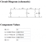
I started with a real midrange driver, the Scanspeak 15M/4531KOO, which has a pleasingly low inductance of 0.17mH, and Re of 3.5 ohms.
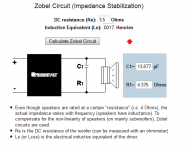
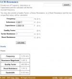
I then calculated the simple Zobel to correct it (assuming linearity, which suits my purposes...LOL) and got 3.5 ohms and 13.9uF. I then calculated the series LCR resonance, and got 3274 Hz.
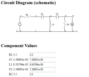
OK, bear in mind 0.17mH, 13.9uF, 3.5 ohms and 3274 Hz. What do you think a third-order Butterworth looks like at 3274 Hz in my preferred matched source/load topology?
Isn't that elegant! There's a pattern there for someone who is paying real attention!
W. Marshall Leach, Jr.
I feel slightly intimidated by the august company in this idea-sharing thread, but care to share an observation about why some combinations of crossover values and drivers might have a sweet spot!
I started with a real midrange driver, the Scanspeak 15M/4531KOO, which has a pleasingly low inductance of 0.17mH, and Re of 3.5 ohms.
I then calculated the simple Zobel to correct it (assuming linearity, which suits my purposes...LOL) and got 3.5 ohms and 13.9uF. I then calculated the series LCR resonance, and got 3274 Hz.
OK, bear in mind 0.17mH, 13.9uF, 3.5 ohms and 3274 Hz. What do you think a third-order Butterworth looks like at 3274 Hz in my preferred matched source/load topology?
An externally hosted image should be here but it was not working when we last tested it.
Isn't that elegant! There's a pattern there for someone who is paying real attention!
Attachments
The SPU Royal N is a wonderful upgrade to the 103r. It improves on every performance area of the 103r and by a wide margin.
The SPU series is the secure upgrade path for anybody who enjoys the 103 series indeed. At $1500 your model though...ouch!
But beautiful, enjoy.Thanks Lynn, if I sounded like I was asking for driver recommendations, it was not the case. I am more interested in the broad strokes rather than specifics.Not off-topic at all
The SPU Royal N is a wonderful upgrade to the 103r. It improves on every performance area of the 103r and by a wide margin.
It does, however, have a very different tonal signature. But different is just that - different.
Lynn, if you notice a change in group delay when you adjust the value of a resistor in a zobel there must be a corresponding change in the amplitude response as well. I can not help but wonder if it is not this change in amplitude, rather than the effect of the zobel on the load the other x-o components see, that is the primary effect.
You mentioned your reasons for using a zobel a few posts ago,
I fail to see how a zobel will isolate nonlinear elements from those which are linear. VC inductance is a nonlinear function of both frequency and displacement. To first order Le can be expressed as Le(F,X) = Le(Fo,Xo) + dLe/dx (X-Xo) + dLe/dF (F-Fo) and all the zobel can do is function as the conjugate to the linear part, Le(Fo,Xo). It thus adds another linear, reactive component in the crossover which interacts with the nonlinearity of the driver's impedance rather than eliminate anything. Certainly R and C of the zobel can be calculated based on Re and Le(Fo,Xo) to form a conjugate, but if the values are to be adjusted based on some other criteria, then they would seem to function as just additional response shaping components.
Looking at the LC part of the crossover, yes, the LC section of the crossover may see a more constant load, but looking back from the driver all that is difference from an LC filter is that C has split into a segment with low series resistance and segment with high series resistance.
Do active crossovers handle these same issues properly? for example can a digital notch serve the same purpose as an LCR trap? Do steeper slopes that avoid the use of passive componenets and time delay solve the need for ladder delay network without adding to the cost and complexity of design?
I guess what Im asking is do you need things like a ZOBEL if you have nearly unlimited sound shaping from active crossovers and EQ?
First, take a look at the figure below. On the left is an typical 2nd order LP filter connected to the driver. On the right is the same circuit except it has a zobel, or does it?
An externally hosted image should be here but it was not working when we last tested it.
I say "does it" because a zobel is a very particular component which is the complex conjugate of the driver's Z. It's had to make a true Zobel with Re and Le are changing as the applied signal changes, and when Le is a function of frequency even when the cone is static. More importantly, for the figure on the left it is the impedance of the driver in parallel with the capacitor, which is then in series with the inductor which will determine the voltage and current the driver sees. On the right, it is the cap in parallel with the series cap/resistor (zobel) in parallel with the driver, all in series with the inductor which determines the voltage and current the driver sees.
If you want to hypothetically make the R/C component a true zobel so that the LC filter sees a pure (or nearly pure) resistive load so the LC filter can be tuned like a text book filter that is fine. But more generally the R/C component can be tuned along with L and C to shape the transfer function in very different ways compared to just the LC filter.
In either case, the two are different circuits and how nonlinearities associated with the driver Z affect the response due to variation of Le and Re with the applied signal would be expected to be different.
If you go active, then the voltage transfer function across the driver should be independent of the driver's Z or the addition of shunt elements, like the zobel, unless the amplifier is sensitive to the load (high output Z amps, for example). However, even in the case of an active filter and use of an amplifier that is insensitive to load, it is only assured that the voltage across the driver will not be affected by changes in Re and Le. The current through the VC will be.
Quite interesting to hear what Marshall Leach says about Zobels. He did a lot of work with realistically lossy voicecoil corrections.
Not quite true, as it goes. John K will be aware of second order crossovers that can incorporate the bass voice coil inductance as a virtual component, but I'm not even going to mention the ****** crossover word since it always seems to start WW3 in this forum!
The whole flat impedance thing interests me, because it is crucial in getting a flat frequency response with zero-feedback, high source impedance amplifiers, or even modern Class D/T designs. .
Dr. Leach's Amplifier and Speaker ProjectsZobel Network Design
(From the book Introduction to Electroacoustics and Audio Amplifier Design, Second Edition, Revised Printing, by W. Marshall Leach, Jr., published by Kendall/Hunt, °c 2001.)
The voice-coil impedance of a loudspeaker driver is not purely resistive. This can have a major perturbation on the performance of crossover networks. At high frequencies, the voice-coil impedance becomes inductive. For odd-order crossover networks, this inductance can be utilized as part of the crossover network. Because the inductance is lossy, some experimentation may be necessary. For even-order networks, the inductance can be cancelled by using a simple RC matching network as discussed below...
Not quite true, as it goes. John K will be aware of second order crossovers that can incorporate the bass voice coil inductance as a virtual component, but I'm not even going to mention the ****** crossover word since it always seems to start WW3 in this forum!
The whole flat impedance thing interests me, because it is crucial in getting a flat frequency response with zero-feedback, high source impedance amplifiers, or even modern Class D/T designs. .
Flat impedance is critical regardless what type of amplification. This means flat impedance of the finished crossovered speaker.Quite interesting to hear what Marshall Leach says about Zobels. He did a lot of work with realistically lossy voicecoil corrections.
Dr. Leach's Amplifier and Speaker Projects
Not quite true, as it goes. John K will be aware of second order crossovers that can incorporate the bass voice coil inductance as a virtual component, but I'm not even going to mention the ****** crossover word since it always seems to start WW3 in this forum!
The whole flat impedance thing interests me, because it is crucial in getting a flat frequency response with zero-feedback, high source impedance amplifiers, or even modern Class D/T designs. .
The type of enclosure also affects the impedance. Some forum users think Speaker Builder old issues are obsolete. Gary Galo did a comparison of mid range drivers in t-lines in issue 2-88. The graphs showed how the bump in the Audax 5' bextene cone at 1500hz was reduced by about 6db. Actually the Audax 5' had a much flatter response then the Kef B110 in the t-line.
Then the question of taper ratio line length and stuffing density all are other topics which affect the overall impedance. I like the sound of tube amps but. A single ended 50 watt tube is not going to play my t-lines subwoofers very loud. Many have claimed high qts. can't be done with t-lines. It was done in the 60's. Using large value air core inductors raises the driver qts.
If I used a iron core inductor the subs would be playting louder then the mid bass and tweeter.
Little did I think that something as simple as a Zobel (I think of them as inductance correctors) would get the forum all stirred up. As mentioned before, I prefer them on subjective grounds, and have been using them since 1975, before the term "Zobel" became common.
I started using them after meeting Laurie Fincham at KEF that same year and learning about what he called "Target Filter Function Design". He mentioned that most midbass drivers are actually mechanically peaked (like MM cartridges) and use a complementary VC inductance that flattens out the published frequency response. The catch is when a designer adds additional inductance in the crossover; that upsets the careful ratio between mechanical peaking and electrical rolloff, so you get an unwanted shelf in the response when additional series inductance is added.
An inductance corrector is a simple way to more-or-less decouple the VC inductance rise from the electrical lowpass filter. In addition to the many different sources of nonlinear inductance (VC position in the gap being only the first of many sources of nonlinearity), VC inductance doesn't even look much like a discrete physical inductor. Getting a really accurate correction for a tweeter, for example, took two sets of inductance correctors, each tuned to a different frequency. Using a single RC corrector circuit results in an approximate correction at best, with several lumps in the overall impedance curve.
Just for grins, one of my later Audionics loudspeaker designs had the impedance resistive all the way to 1MHz; I was concerned about transistor amps with doubtful phase margin and the resulting impact on sonics (longer settling time from a slewing event) and reliability. Since I never auditioned the T-52 on a really bad amplifier, I wasn't sure if the extra-extended inductance correction was worth it or not.
This was during the design of Bob Sickler's CC-2, where he went to a lot of trouble to give the amplifier both a high slew rate and also a high phase margin (an unusual combination at the time, when the relationship between slew rate, settling time, phase margin, and reactive loads was not that well understood).
These days, I design loudspeakers for direct-heated-triode and pentode/beam-tetrode amplifiers with zero to moderate feedback ratios, and power ratings in the 3~60 watt range. There are lots and lots of audiophile speakers on the market that are suitable for 100~500 watt Class AB (or Class D) transistor amplifiers.
Since I have the luxury of designing both the power amplifier and loudspeaker, I could go off into the never-never land of current-drive interfaces, or dedicated multi-amp setups with electronic EQ, but that has the drawback of making speaker and amplifier comparisons impossible, so I stick to industry-standard interfaces.
Last edited:
I kind of glossed over the relationship between slew rate, settling time, phase margin, and reactive loads.
Feedback amplifiers take a certain time to return to zero after a slewing event (slewing is when an internal stage of the amplifier has insufficient current to charge an internal capacitance). This return-to-zero after slewing is known as settling time, a common specification in high-performance opamps. Settling time is increased when an amplifier moves closer to oscillation, or in other words, has less phase margin.
Phase margin, in turn, is influenced by the reactance of the load at high frequencies (typically, for transistor amplifiers, frequencies above 100 kHz, and as high as 1MHz). If the load is reactive enough, it can tip the amplifier into full-blown oscillation (unmistakable on a scope as fuzz on the trace), or short of that, into extended settling time.
So the settling time of an amplifier is partially a function of the HF reactance of the speaker + speaker cable load. Ordinary speaker cables are typically inductive, but there's been a modern fad for high-capacitance speaker cables, on the grounds that inductance is "bad". This makes zero sense to me, but I can't stop industry fables from spreading all by myself.
Transistor amps really don't like reactive loads at HF, and the internal decoupling networks are only partially effective. Not only that, these networks can be responsible for AM-radio frequencies going through the feedback resistor and getting rectified in the input transistors. Speaker cables make pretty good AM-radio antennas, so this can be a real problem - even if the AM interference is not audible as Rush Limbaugh or a radio evangelist in the background, it can raise distortion levels on an intermittent basis, since the RFI drives the input stage into nonlinear regions, depending on modulation levels.
Getting a high-feedback transistor amplifier to be RFI-resistant and tolerant of weird speaker cables is not a trivial enterprise, and worse, depends a great deal on where the customer lives and the arcana of how speaker cables pick up ambient RF fields. Even moving a cable a few feet can have a substantial effect on RFI pickup.
Taking a different approach, zero feedback means no path from the speaker cable to the input stage. Vacuum tubes also tolerate RFI better, since they are linear right through RFI frequencies. My amplifiers use input transformers, which break the chassis-to-chassis ground connection (no ground loops), as well as rejecting RFI. So the net result is an amplifier that is resistant to RFI and ground loops. But I am well aware that transistor amplifiers are quite susceptible to RFI on both the input and output cabling, and settling time from slewing is affected by the HF characteristics of the speaker load.
Last edited:
Hey Lynn
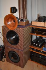
From page 87 to today---from OB to sealed
With months of Q/A help from ScottG I built these double sand filled sealed low Q enclosures for both the GR research servo subs and AE TD 12M's. The horns CD's are still Radian 745's and a pair of Fountek 3.5 ribbons . Thanks again Lynn , Gary D and ScottG for all your help. SET, horns and servo subs are a wonderful match .
Greg
Attachments
I Taking a different approach, zero feedback means no path from the speaker cable to the input stage. I am well aware that transistor amplifiers are quite susceptible to RFI on both the input and output cabling, and settling time from slewing is affected by the HF characteristics of the speaker load.
Lynn, other amp designers have adopted a philosophy to isolate the output grunge from sensitive input circuits.
From what I have read, Dan's D'Agostino's recent Momentum amp does not have global feedback from the output to the input, but it does have (patented) nested feedback over the input stages plus (large amounts of) error correction feedback on the output stage.
The Momentum design goal appears to focus on isolating output noise from the high sensitivity diff input. To me, this is an interesting discussion point.
1) The reverse currents from high inductance speaker voice coils can affect the sound if they are fed back to the high gain differential input stage.
2) All Krell amp schematics I have seen use MOSFETs for the first output driver stage with the goal of isolating the speaker's reverse currents from the gain stages. I do not know if the Momentum design includes this voltage-to-current isolation. John Curl's amps also use a MOSFET output driver for this same isolation goal.
3) RFI noise, especially from digital Wi-Fi networks and in-home local networks, can get picked up on the speaker interconnect cables and fed back to the high gain differential input stage.
4) Nested feedback, like TMC, over the high frequency, low capacitance input stages is more accurate than global feedback that goes around the 24-pair Momentum output stage. Very little noise gets injected into the intput stage loops.
The gotcha with MOSFETs is the extremely high gate capacitance (in the 500~1000 pF range) that is (very) nonlinear with respect to current density. This is especially troublesome in the transition from Class A to Class AB, when both sexes of device operating in parallel transition from the Class A region to one sex only (the Class B region). Local feedback, feedforward, or a sophisticated analog computer, is almost essential to smooth out the transition region. Unfortunately the transition from Class A to Class AB occurs in the 1~3 watt range for most MOSFET amplifiers, which isn't such a good location in terms of dynamics.
There's pseudo-Class A, which are typically idling schemes to prevent device shutoff, but that's not the same as having both sexes remain active over the entire duty cycle. Thermal Class A, or "real" Class A as used in the textbook, dissipates a tremendous amount of heat, requiring power derating or active cooling. One subtle advantage of vacuum tubes is they inherently run hot, act as their own heatsinks, and capacitance and current gain are not modulated by temperature differences (unlike solid-state devices, where die temperature is a critical operating parameter).
Although vacuum tubes have excellent inherent linearity and have stable and low-distortion grid capacitances, the power limitations are pretty strict. Power supplies in the 350~500 volt region only yields a modest amount of power (20W typical) if the amplifier is restricted to true Class A operation. Once you go much beyond 500V rails, transmitter-style construction is required, and costs rise very rapidly. In addition, output transformer performance goes downhill thanks to higher operating impedances, which degrades bandwidth.
There's no free lunch. If real, thermal Class A operation is desired, then very large heatsinks are required, even for modest power outputs, or self-heatsinking vacuum-tubes are chosen, which have their own set of limitations. Many marketers have made bold claims for pseudo-Class A over the last forty years, but non-thermal approaches only solve problems with abrupt on-off switching transitions, but do nothing for the large shifts in current gain as pairs of devices are switched in and out of the circuit. Supplementary circuitry to soften the transition helps, but is not the same as keeping all the devices amplifying over the entire duty cycle.
If the devices on both sides of the circuit are symmetric (including matched capacitances for pairs of devices) significant gains in linearity can be realized. With Class AB operation, most of the symmetry improvement is traded for increased efficiency. (Symmetrical operation, by definition, does not occur when only one side of the circuit is amplifying, so there are no distortion-cancellation benefits in the Class B region. These benefits only happen when both sides of the circuit are symmetric, have no time-delay differences between the two sides, and both sides have reasonably similar forward gains.)
These hard, brickwall limitations in power amplifiers are much of the reason I am designing a higher-efficiency loudspeaker. Sure, 500 watts are easy if Class AB, Class D, or Class G/H operation is acceptable. Traditionally, Class A is the mode of choice for the highest-quality applications. You don't see Class AB mike preamps or phonostages, do you?
Class AB has always been about watts-per-dollar. It has been has been more and more necessary as speaker efficiencies declined in the late Fifties, through the Sixties, and hit bottom in the Seventies, when well-reviewed speakers (with Bextrene cones) fell in the 82~85 dB/meter range, a historic low. Efficiencies slowly crept up in the Eighties and Nineties, with most high-end audiophile speakers falling into a (genuine) 87~92 dB/meter range. (Efficiency claims of 95 dB/meter, or higher, for loudspeakers with a complement of conventional direct-radiator drivers are usually fictitious, especially if the manufacturer does not publish frequency-response curves.)
Raising efficiency into the 97~102 dB/meter range has a whole different set of challenges. Woofers can be paralleled or fronthorn loaded, both of which increase size and cost. High-efficiency direct-radiator midranges are thin on the ground, but modern ribbons and Heil AMT tweeters have pretty good efficiencies.
The traditional tradeoff for high-efficiency speakers has been degraded impulse response - specifically, long settling times with chaotic decay characteristics. Audiophiles had to choose between high-efficiency speakers with not-so-good time and dispersion characteristics while enjoying the benefits of low-distortion Class A amplifiers. Or, they could choose low-efficiency speakers with good time characteristics, and settle for Class AB transistor amplifiers with global or multiple feedback loops. Both types of sound had inherent virtues and deficits.
With more interesting amplifiers on the market, and improvements in loudspeakers, the traditional either/or choice is broadening into a wider sonic palette.
Last edited:
Although not mentioned above, the capacitances for PNP and NPN devices are usually different by 2:1. You can get very good complements in the DC sense, but at high frequencies, the transit time through the two halves of the circuit are not the same, which leads to phase differences when the signal is summed at the output. The NPN/PNP difference in gate or base capacitance also leads to different switch-on and switch-off times for the Class AB output devices, which is why additional small capacitors are sometimes seen on one side of the circuit.
What is frequently overlooked in symmetrical circuits is phase symmetry when the signal is summed at the output (or in an intermediate stage). To realize even-harmonic distortion cancellation, the vectors have to be opposite each other, as well as matched in magnitudes. A 5-degree phase shift in vectors is about equal to a 3% gain mismatch, so small phase differences matter.
To cancel odd-harmonics, the Western Electric Harmonic Equalizer (dating from the early Thirties) is required. John Atwood is working on an article on this in an upcoming magazine, so stay tuned.
Although Bell Labs invented negative feedback, they chose negative feedback for the single-ended 91A theater amplifier, while the push-pull 92 and 86 amplifiers used the Harmonic Equalizer instead of negative feedback. The later pentode amplifiers, though, did use negative feedback.
Last edited:
Hey Lynn
From page 87 to today---from OB to sealed
With months of Q/A help from ScottG I built these double sand filled sealed low Q enclosures for both the GR research servo subs and AE TD 12M's. The horns CD's are still Radian 745's and a pair of Fountek 3.5 ribbons . Thanks again Lynn , Gary D and ScottG for all your help. SET, horns and servo subs are a wonderful match.
Greg
I see that ScottG is using the latest 18Sound ND1480A's with good results. Does he have any comments on the sonics and measurements of the Radian 745 versus ND1480A's?
- Home
- Loudspeakers
- Multi-Way
- Beyond the Ariel