We willbe selling three items, PCB, Programmed PIC, and parts kit.
PCB: $12
PIC: $3
Complete Kit (with PCB, PIC, et al): $55
If you are buying the board and programing your own PIC, get the $12 option. If you get our board and don't want to program your own PIC, but want to get your own parts, $12 + $3. If you just want everything to start building, that's the complete kit.
We will be shipping the beta test kist in the next week or two. After we get some feedback from those, we will ramp up production shipping as quickly as possible.
Most of the kit cost is from the PGA2311 and AD8620. We also include mounting hardware, heatsinks for the regs, thermal pads, pot, pin headers, etc. Everything you should need.
[EDIT] I also got some Amveco 7VA 12+12 torroids for the beta test. They are super small. We will probably have those as well for about $13-$14 each. One will be enough to power the pre and the source selector (coming soon).
One will be enough to power the pre and the source selector (coming soon).
Another "source selector" tease!

Can't you give us a tiny, teeny weeny little preview of what we can expect?

On a serious note than: Brian, did you already received my payment for the pre-amp kit?
Cheers
Yes, I did.
We are still working out some details on the source selector, but here is a little info.
3-source, relay switched. 2-output, relay switched (can have both active). Optional and selectable buffer on the output, again relay switched. LED out for each option. It will be PIC controlled.
There will be a set of pin headers for the inputs. Connecting an input to ground selects it. The header will also supply +5VDC incase you want to use some sort of active switching.
Basically, you could use any kind of momentary of continuous switch to control it. I am going to be making a touch-sensitive switch board using the QProx chips in momentary mode (for me), powered off the +5VDC out of the SS.
At this point we are testing for switching noise etc. Seems to be going quite well. The trick is that it's a double-sided board only (to keep it small) so we will need to get some prototypes made. We will be starting a thread very soon.
Source Selector
Ok posted a new thread for the source selector. It is nearing completion.")
http://www.diyaudio.com/forums/showthread.php?s=&threadid=66546
Ok posted a new thread for the source selector. It is nearing completion.
http://www.diyaudio.com/forums/showthread.php?s=&threadid=66546
Where do I order? Or can I not because it's still in beta (I'd offer to help w/ beta-testing, but I only have old [1970's] JVC/HMV amps and old JVC/Marantz speakers to test try onBrianDonegan said:If you get our board and don't want to program your own PIC, but want to get your own parts, $12 + $3.
)Do the SM ICs or the 2311 need cooling? Or only the TO-220 chips?Most of the kit cost is from the PGA2311 and AD8620. We also include mounting hardware, heatsinks for the regs, thermal pads, pot, pin headers, etc. Everything you should need.
Is it possible to get a B.o.M for this?
So 7VA @ 12V should be enough for both? If I put in the buffer to power my 'phones as well, would I need a more powerful trafo? I'm tossing up between the 20VA (0.83A on each 12-0-12) and the 7VA ones from Jaycar.I also got some Amveco 7VA 12+12 torroids...One will be enough to power the pre and the source selector (coming soon).
Sorry about all the questions guys
Cheers,
--Nathan
They are still in Beta, so no ordering yet. Making sure we don;t need to change anything before we move forward. It's possible the parts BOM will change, but we will know very soon. Pricing would then change accordingly, but I think these will be the final numbers.
Only the VRegs have heatsinks. Other chips stay nice and cool (well, so far as we have seen in the protos, but I don't expect that to change).
We think 7VA should be enough. No harm in using something larger. Last night I was powering a prorotype Kookaburra (home etched) and 6 relays simultaneously off one of the little trafos (actually sharing the 7812 from the pre - the switcher does have it's own vreg though). Everything was fine. The relays are only drawing about 70mA total. If 7VA proves too small in ours tests, we will select a larger version.
home to roost!
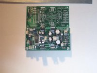
Got home from work, and a whole flock of Kookaburras was on my porch. Anyway the PCBs are great! A little annoying issue with the silkscreen made some of the lettering run into some hole, but nothing important.
Anyway, the thing sounds even better now that it has a serious ground plane and noise floor is even lower than before. The input buffer does seems to help the low end, even with ordinary (low Zout) sources. Probably because it increases the Zin.
Overall, I am very satified, and it should be a relief to the beta builders that you can be sure the PCB is OK.
Has to be a record build for me, only took about an hour.
Now time for some pumpkin ale.
Cheers!
Russ
Attachments
Looking good Russ 
Does that stuff realy exist!
Regards
Now time for some pumpkin ale.
Does that stuff realy exist!
Regards
GeWa said:Looking good Russ
Does that stuff realy exist!
Regards
Thanks!
Yes, but it really does not have pumpkin in it, just pumpkin spice, which is clove, nutmeg, and cinamon. It by the Shipyard Brewery here in the states, and it is called "Pumkin Head Ale" and it is really very good.

Cheers!
Russ
float said:Hi Russ, just wondering if one pot and one PIC could control say three PGA chips for a six channel volume control. Might be useful for the digital active crossover crowd (maybe me one day
Well, the short anwser is yes, if you added one more control to the select the channel to be adjusted... but, I would not implement it as such.
If I were to try it, I would do it as I have with the 5.1 pre I am working on, and use a push-in switch type rotary encoder.
One cool thing about the kookaburra PCB though is it would be very simple to control one or more kookaburras from an external controller board, and you could do it several ways. You could simply omit the PIC and run wires to an external PIC through a header or something, or you could leave the PIC on the kookaburra, an run a 3 wire cable from the pot header to a digitally controlled analog pot. Maxim has a ton of those type pots to choose from.
The first give you the most flexibility, as you could control two channels independantly.
You could even tap the "SO" pin from the PGA2311 on one PCB and wire it to the "SIN" pin of the PGA2311 on another PCB and then join DGND, SCLK,and CS as well, then you for a large shift register and could control N number of channels, but you would need to rewrite the PIC code to handle that.
You would also want to use a rotory encoder/remote reciever or something as I mentioned earlier to get the input from the user.Pheeeew that is hard to explain quickly, I prolly completely botched it up.
Cheers!
Russ
Russ White said:
Well, the short anwser is yes, if you added one more control to the select the channel to be adjusted... but, I would not implement it as such.
If I were to try it, I would do it as I have with the 5.1 pre I am working on, and use a push-in switch type rotary encoder.
Russ
Rotary encoders are comparatively expensive -- for a darkroom controller I built I used pushbutton "up" and "down" -- with a routine that accelerated the increments the longer the button was held.
Of course, you can make it overly complex like the clock in my new car -- it requires a master's degree from Carnegie Mellon to program the darned thing.
True, a lot of rottary encoders can be expensive, especially the optical ones. I found a pretty good mechanical one for about $4US though, and it is working great, and thats really less then some quality pots.
Push buttons are certainly another excellent option.
That reminds me....
One feature I added to the code for the Kookaburra is a turn on "ramp up" time about about 3-4 seconds. So, the volume comes up to the current setting on a curve, so if you left it on full tilt when you turned the preamp off and forgot, or your child turn the knob completely clockwise... when you turn the thing back on you won't be as likely to blow a speaker, or an eardum.
Cheers!
Russ
We are looking at a rotary encoder in the $3-4 range, designed for car radios and nav systems. Another nice thing about the encoder is that it's easy to integrate into your front panel without a lot of machining. Buttons are easy too, but it's hard to find ones that aren't ugly.
We are also designing a touch-sensitive interface for the source selector, but it could be used for other applications as well, such as up/down volume control. It will use QProx chips. Very simple and inexpensive to do.
We are also designing a touch-sensitive interface for the source selector, but it could be used for other applications as well, such as up/down volume control. It will use QProx chips. Very simple and inexpensive to do.
Russ White said:
Well, the short anwser is yes, if you added one more control to the select the channel to be adjusted...
I was actually just hoping 3 wires from the pic to three PGA chips would be an accurate six-gang pot. I wasn't thinking of balance adjustments between channels, if thats what you're referring to .
I can tell I'm out of my depth here.......
float said:
I was actually just hoping 3 wires from the pic to three PGA chips would be an accurate six-gang pot.
Oh sure you could indeed do that if you could find a 6-gang pot. Not sure I have ever seen one, but that does not mean they don't exist.
If you wanted them all to have the same volume, one other easy thing to do would be to take 3 PCBs and have them all share a common digital PS.
Notice the pot header has +5V, WIPER, and DGND pads.
So you would omit JG and R1 on the 2 "SLAVE" boards. You would then run a wire from the +5V pad on the "MASTER" PCB to the +5V pad on each "SLAVE" PCB. And you would likewise run a wire from DGND on the "MASTER" PCB to the DGND of each "SLAVE" PCB.
Then you would take the 3 wire cable from the "MASTER" PCB to a singal 5K linear pot. You would then run a single wire from the "WIPER" pad on the "MASTER" PCB to the "WIPER" pad on each of the "SLAVE" PCBS leavbing the other to pads empty. Then all 3 PCBs will use the same volume pot, and will have the same volume setting.
The easier way to do that would be that when you make your 3 wire connector for the POT header, you use two wires for each PIN(5V,wiper,GND), would would then put a second connector on one set, and the other set you would run to the POT. You could thus "daisy chain" the boards together, the important thing is that they all share a common PS, so omiting R1 and JG is important for the slave boards.
Ok one further thought, but maybe this is way over the line. But hey I am having fun.
You run a master pot from one PCB, and run the wiper of that pot to one end of a seperate additional pot on each PCB with the other end of each of those pots being GND. Then you should adjust the level of each PCB individually relative to eachother, but they would all go up and down with the "master" pot.
If you parelleled the output of each PCB you could run 6 PCBs for truly independant 5.1 audio.
A little far fetched, but it would work!
If you were not interested in left/right adjustments you could actually do it with just 4 PCBs, one for LF/RF one for LS/RS and one parallel for Center and one paralelled for SW.
Maybe I should try to illustrate that....
:EDIT: clarified a bit
But hey I am having fun.You run a master pot from one PCB, and run the wiper of that pot to one end of a seperate additional pot on each PCB with the other end of each of those pots being GND. Then you should adjust the level of each PCB individually relative to eachother, but they would all go up and down with the "master" pot.
If you parelleled the output of each PCB you could run 6 PCBs for truly independant 5.1 audio.
A little far fetched, but it would work!
If you were not interested in left/right adjustments you could actually do it with just 4 PCBs, one for LF/RF one for LS/RS and one parallel for Center and one paralelled for SW.
Maybe I should try to illustrate that....
:EDIT: clarified a bit
Russ White said:But hey I am having fun.
Maybe I should try to illustrate that....
While your having fun.....
Try designing it! I'd buy one!
Also couldn't you get away with 3 brds if you put the center on one channel and the sub on the other? Since MOST subs have level controls built in...
- Status
- This old topic is closed. If you want to reopen this topic, contact a moderator using the "Report Post" button.
- Home
- Amplifiers
- Headphone Systems
- Digitally controlled preamp/headphone amp