Re: Programming
Nothing major really.") I use a PICKit2 programmer which you can get for less than $50US from www.microchip.com
I use a PICKit2 programmer which you can get for less than $50US from www.microchip.com
The PIC to use is either the PIC12F675 or PIC12F683 either will work. You can get those as samples from microchip.
I used PICC to compile the C code, and MPLAB as the IDE all of which you can get for free.
MPLAB comes with the PICKit2 package, along with some other goodies.
If we decide to sell kits for these things they will come with a pre-programmed PIC.
You can also get all sorts of programmers for the PIC devices, many DIY.
Cheers!
Russ
maf_au said:Russ,
What's involved in programming the chip in this project? I've played with a lot of software/hardware, I'm not a programmer but that's never stopped my from having a go.
Michael
Nothing major really.
I use a PICKit2 programmer which you can get for less than $50US from www.microchip.comThe PIC to use is either the PIC12F675 or PIC12F683 either will work. You can get those as samples from microchip.
I used PICC to compile the C code, and MPLAB as the IDE all of which you can get for free.
MPLAB comes with the PICKit2 package, along with some other goodies.
If we decide to sell kits for these things they will come with a pre-programmed PIC.
You can also get all sorts of programmers for the PIC devices, many DIY.
Cheers!
Russ
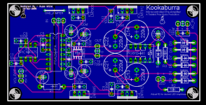
Ok so here it is with the leakage preventing relay and double sided. The circuit is tested and works exactly as designed, but I have not had a chance to test this two sided layout. If I can get about 5 beta testers to pitch in for PCBs I will order some for us to test.
This version uses the SMT(SOIC) AD8620, I am also considering a DIP version, but that severly limits your choices for dual opamps, especially really super good ones like the AD8620(which you cannot get in DIP).
Have a gander.
This version uses the SMT(SOIC) AD8620, I am also considering a DIP version, but that severly limits your choices for dual opamps, especially really super good ones like the AD8620(which you cannot get in DIP).
Have a gander.
Attachments
Russ
Wouldn't it be advisable that al the components regarding to the PIC controller would be on the same groundplane. This would mean that IC1, IC2, C3, C4, C10 and C11 have to be relocated towards the area of the PIC. This also creates space to rearange caps closer to the PGA.
Can you give some more specifics on how you see the "Beta Testing
Regards
GeWa said:Russ
Wouldn't it be advisable that al the components regarding to the PIC controller would be on the same groundplane. This would mean that IC1, IC2, C3, C4, C10 and C11 have to be relocated towards the area of the PIC. This also creates space to rearange caps closer to the PGA.
Can you give some more specifics on how you see the "Beta Testing
Regards
Actually, all of the components that are exclusive to the PIC and the digital side of the PGA2311 are already on the digital ground plane.
Also, the isolation of the ground planes is as perscribed on the datasheet.
The LM7805 regulator is shared between analog and digital. This arrangement has been tested with great results, also it is almost exactly the same arrangemnt used on the datasheet.
Cheers!
Russ

good morning Russ& Brian;
If you can spare a board for the new pre amp I definitely have the time to build it. It would help a lot if Brian could assemble the parts; or a b.o.m. and the best place to obtain the parts.
Have you considered designing and building a phono stage?:
cheers
doggy
If you can spare a board for the new pre amp I definitely have the time to build it. It would help a lot if Brian could assemble the parts; or a b.o.m. and the best place to obtain the parts.
Have you considered designing and building a phono stage?:
cheers
doggy
for uP-hating people...
like me, why do not gibve a try to:
http://www.national.com/pf/LM/LM4811.html
pushbutton volume control, buffer, headphone out in a single chip.
National semiconductor, like the My_Ref part kit.
like me, why do not gibve a try to:
http://www.national.com/pf/LM/LM4811.html
pushbutton volume control, buffer, headphone out in a single chip.
National semiconductor, like the My_Ref part kit.
Re: for uP-hating people...
Hi plovati,
A couple of reasons:
1) The volume control is intentionally by pot, not push button. This is actually a feature to myself and a few others who wanted this thing.
2) The LM4811 has pretty bad THD compared to the Burr Brown part at .1%.
3) This design is complete, tested, and sucessfull.
There are other points, but those are enough.
Now that does not mean the national chip would not make a good project, its just not this project.
Cheers!
Russ
plovati said:like me, why do not gibve a try to:
http://www.national.com/pf/LM/LM4811.html
pushbutton volume control, buffer, headphone out in a single chip.
National semiconductor, like the My_Ref part kit.
Hi plovati,
A couple of reasons:
1) The volume control is intentionally by pot, not push button. This is actually a feature to myself and a few others who wanted this thing.
2) The LM4811 has pretty bad THD compared to the Burr Brown part at .1%.
3) This design is complete, tested, and sucessfull.
There are other points, but those are enough.
Now that does not mean the national chip would not make a good project, its just not this project.
Cheers!
Russ
Re: getting closer....
well, to avoid noise from random variations on the LSB of the ADC I would (as Mauro was suggesting) add a "threshold" to that:
Threshold should be a value chosen to correspond to the minimum volume variation you want to consider. Of course, to be effective it must be > than the LSB of the ADC.
Russ White said:Code:if (value != last) { writeState(value); last = value; }
well, to avoid noise from random variations on the LSB of the ADC I would (as Mauro was suggesting) add a "threshold" to that:
Code:
		if abs((value - last)) > THRESHOLD {
			writeState(value);
			last = value;
		}
Threshold should be a value chosen to correspond to the minimum volume variation you want to consider. Of course, to be effective it must be > than the LSB of the ADC.
Hi unixman, not a bad tip, but I have a 10bit ADC and am throwing away the least significant bits. I want to be able to use all 256 step on the volume control so I have implemented it as you see, with great success.
So you see it is a simple 8bit to 8bit comparison.
So I am not sure there is any value in a threshhold, but maybe I am confused.
The program works perfectly as intended. The scope shows serial communication with the PGA2311 only when desired(256 steps).
Cheers!
Russ
So you see it is a simple 8bit to 8bit comparison.
So I am not sure there is any value in a threshhold, but maybe I am confused.
The program works perfectly as intended. The scope shows serial communication with the PGA2311 only when desired(256 steps).
Cheers!
Russ
before you send the boards out, as you are in a physics lab I am led to understand you have access to a decent spectrum analyzer (i.e. not a soundcard which is limited to 22kHz) -- try this -- take a matchstick and wrap about 40 turns of #40 enamel wire around it. make a probe with a non-inductive 49.9R resistor and the coil in series. connect to a spectrum analyzer like an HP3585A. carefully sweep around the board.
don't squirm, don't squalk, don't take offense, just perform the experiment as directed, take two tylenol and report back to us.
don't squirm, don't squalk, don't take offense, just perform the experiment as directed, take two tylenol and report back to us.
- Status
- This old topic is closed. If you want to reopen this topic, contact a moderator using the "Report Post" button.
- Home
- Amplifiers
- Headphone Systems
- Digitally controlled preamp/headphone amp