Did you insulate the transistors from the heat sink?
I used grease previously but I don't have any heat sinks on them now as they don't get hot at all biased with two diodes.
I replaced all the resistors on the R side with carbon nos. Works fine. The resistors on the output did what they are supposed to do, burned up with something going to ground. I have no idea how it did but it had to have. Keeping my eye on it right now but the two 4.7 resistors are running cool and the sound is well balanced. Now I will replace the L channel with carbon. Eventually I would like to use Riken Ohm or most likely Kiwame if I can find the right resistance. Tantalums are my preference but non of my NOS are the right value and new stuff is too expensive and frankly I think the Kiwames do a very good job.
Last edited:
Mutual Inductance paths for current -
I mentioned that pcb traces for power supply need to have their own ground trace running under it, didnt I?
Ground planes act as a wire at the higher audio frequencies for same reason.
This is a visual of what I am talking about ---> It isnt just at RF this happens;

THx-RNMarsh
I mentioned that pcb traces for power supply need to have their own ground trace running under it, didnt I?
Ground planes act as a wire at the higher audio frequencies for same reason.
This is a visual of what I am talking about ---> It isnt just at RF this happens;
THx-RNMarsh
Important and interesting information as is your information on creating a hole through the ground plane creating eddy currents.I mentioned that pcb traces for power supply need to have their own ground trace running under it, didnt I?
Ground planes act as a wire at the higher audio frequencies for same reason.
This is a visual of what I am talking about ---> It isnt just at RF this happens;
View attachment 455937
THx-RNMarsh
I replaced all of the 4.7ohm and 10 ohm (18ohm on the board but 10 on the board I got) with NOS carbon resistors. They are 2 watt, all they had in nos carbon here locally so everything is taking its time to settle but the sound is expansive, great bass and very transparent. I prefer them to the magnetic resistors provided in the kit.
I also wonder about the NTE185 and 184. I have read they have closer tolerances.
I also wonder about the NTE185 and 184. I have read they have closer tolerances.
I got my PCB and parts from jack and am soldering them now.
There are 4 spots that have through holes with no designator ... are these jumpers or should they just be ignored?
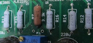
Also, my parts kit came with a mix of CMF55 and CMF60 3.3K resistors and the latter don't fit the PCB hole spacing ... just an FYI ... I can order some extra CMF55's in my next Mouser order.
There are 4 spots that have through holes with no designator ... are these jumpers or should they just be ignored?
Also, my parts kit came with a mix of CMF55 and CMF60 3.3K resistors and the latter don't fit the PCB hole spacing ... just an FYI ... I can order some extra CMF55's in my next Mouser order.
I got my PCB and parts from jack and am soldering them now.
There are 4 spots that have through holes with no designator ... are these jumpers or should they just be ignored?
Also, my parts kit came with a mix of CMF55 and CMF60 3.3K resistors and the latter don't fit the PCB hole spacing ... just an FYI ... I can order some extra CMF55's in my next Mouser order.
The jumpers can be used for a better grounding scheme. This is explained by Richard Marsh further back in the thread. I used all 4, jumping them.
Were your output devices the same brand? My L and R were different. I asked for the same brand for the R, to match the brand used and shown in the schematic and are used on the L channel but never received a reply.
Thanks ... went back through the whole thread and found the jumper discussion. The discussion is very confusing to say the least. After looking at the PCB, all it does is tie the "shield plane" on the bottom to Ground ... and if you look close, it only does so on one side of the PCB ... the other side is missing the thermal ties on the vias, so a jumper would do nothing on that side.
My output devices were the same brand but my JFETs were not (L to R).
I thought I looked close enough at the schematic. I am pretty sure that Richard Marsh tied them all together. I would imagine he will have an answer to this question.
The jumpers can be used for a better grounding scheme. This is explained by Richard Marsh further back in the thread. I used all 4, jumping them.
Were your output devices the same brand? My L and R were different. I asked for the same brand for the R, to match the brand used and shown in the schematic and are used on the L channel but never received a reply.
You got a board which was soldered together, pre-tested and tweaked to THD% below 0.001%
WRT the CMF60 resistors -- there was also 3.3k CMF55's in the package.
Now I know the reason the folks in Benton Harbor were always pulling their hair out!
Last edited:
My board? No sir ... my board was never soldered. The thermals missing from the vias is an artwork error in the Gerber and nothing to do with soldering, etc.You got a board which was soldered together, pre-tested and tweaked to THD% below 0.001%
True, but not enough to build the board. My OCD won't let me put 3 CMR60's on a PCB when the rest are CMF55's.WRT the CMF60 resistors -- there was also 3.3k CMF55's in the package.

And what reason would that be?Now I know the reason the folks in Benton Harbor were always pulling their hair out!
Benton Harbor was full of bald guys, mostly dealing with issues related to kits soldered with acid-core solder.
jamato's board was tested. he subsequently had a problem with the 4.7R resistors, but neglected to use an insulator between the output transistors and heatsink (grease is not an insulator.) at idle, the amplifier draws about 110 to 130mA and the output transistors are "very" warm-to-the-touch, but not hot.
That the signal ground and ground power plane are not connected and is not an error in the Gerbers, but to allow the two nodes to be connected at the user's discretion.
Use the CMF60's for the feedback resistor, the CMF55's on the drains of the jfets, a la:
Attachments
That the signal ground and ground power plane are not connected and is not an error in the Gerbers, but to allow the two nodes to be connected at the user's discretion.
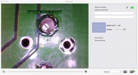
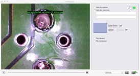
Take a look at the screen caps below. One channel the via in the "ground plane" has thermal ties. On the other channel it is floating, so soldering a jumper will do nothing.
This sure looks like an error to me!
Attachments
Benton Harbor was full of bald guys, mostly dealing with issues related to kits soldered with acid-core solder.
Heathkit!
Benton Harbor is only about an hour south of me ...
You got a board which was soldered together, pre-tested and tweaked to THD% below 0.001%
WRT the CMF60 resistors -- there was also 3.3k CMF55's in the package.
Now I know the reason the folks in Benton Harbor were always pulling their hair out!
I got two kits. One that was not soldered, stuffed, for a friend and the one that you put together as you stated that these were the two that you had (kits). I know that the grease is not insulation but if the heat sinks are Not touching, they create no problem, having worked with very high voltage in this area (transistors), I do like to use insulators but that is for a safety reason and it only creates a problem if they touch (the heat sinks) each other or ground out, which the heat sinks I used for this kit did not.
I had no extra resistors in my kit. Tear your hair out if you enjoy that or respond to a customers legitimate questions. Maturity would advocate for responding in a professional manner but the choice is yours.
Supplying different brands of output transistors matched or not, is not the normal course in audio. I have used tubes for years and by way of matching, it is not only voltage and current properties but also manufacture as materials can vary and this goes to sound, which the human ear is often more adept at determining than measurements. I had asked you about the output devices a few times in emails and you chose to not respond. Also the resistors on my board are not the same either. You chose vishay/dale for one side and some other metal film for the other side. No extra resistors were included.
Last edited:
I got two kits. One that was not soldered, stuffed, for a friend and the one that you put together as you stated that these were the two that you had (kits). I know that the grease is not insulation but if the heat sinks are Not touching, they create no problem, having worked with very high voltage in this area (transistors), I do like to use insulators but that is for a safety reason and it only creates a problem if they touch (the heat sinks) each other or ground out, which the heat sinks I used for this kit did not.
I had no extra resistors in my kit. Tear your hair out if you enjoy that or respond to a customers legitimate questions. Maturity would advocate for responding in a professional manner but the choice is yours.
Supplying different brands of output transistors matched or not, is not the normal course in audio. I have used tubes for years and by way of matching, it is not only voltage and current properties but also manufacture as materials can vary and this goes to sound, which the human ear is often more adept at determining than measurements. I had asked you about the output devices a few times in emails and you chose to not respond. Also the resistors on my board are not the same either. You chose vishay/dale for one side and some other metal film for the other side. No extra resistors were included.
You had P and N devices, uninsulated, on the same heat sink.
You had P and N devices, uninsulated, on the same heat sink.
No I did not. They have their own heat sink, individual ones. Who ever said I had them on the same one? That would be ignorant, and after one try, would be rectified with finding out what happens.
Last edited:
- Home
- Amplifiers
- Headphone Systems
- Marsh headphone amp from Linear Audio