Low volumes, I suppose, and perhaps the difficulty of getting BJT-like DC performance from an integrated FET input stage.
Well, you are talking about op amps you just don't know it yet.
An op amp isn't defined by being an integrated circuit, it's a differential, high open loop gain (voltage) amplifier with global feedback. The OPA134 is an opamp (integrated circuit), those 2520 modules are too (as a discrete, pre-built package) and whatever I would come up for a native Sapphire front end would most likely also fit the description.
My resistance to going down that route is,
1. Board real estate.
2. BOM spiraling out of control.
3. The low ROI on reinventing the wheel.
The John Hardy white paper disfunctionalshadow linked to above makes the best case I've yet read for why discrete op amp should sound better than integrated, but I'm still not convinced the humble OPA134 is so bad in comparison [in the application of the Sapphire circuit...], or that anything I could manage would be substantially better than both.
As for "hype", would you consider $60 US for a MUSES01, essentially a poorly performing OPA2134 variant?
OK, I knew that, I've read Nelson Passes paper on opamps
") In fact I read it again last night wondering if I should make my own opamp. After following this thread I looked up opamp rolling and came across the Audio-Gd discrete opamps and Burson etc.
In fact I read it again last night wondering if I should make my own opamp. After following this thread I looked up opamp rolling and came across the Audio-Gd discrete opamps and Burson etc. I'ts an interesting point you raise about opamps. If IC are good for front end, then wouldn't the new national current buffer be a worthwhile output stage? You could parallel then even. Perfectly matched transistors on one die.
I'm not certain a discrete opamp would be better, but its sort of a natural evolution of this wonderful amp
The Muse chip is not for me, I think I would go Burson first to satisfy my curiosity regarding discrete, but they are expensive too, I think around $60.00 dollars a piece. Maybe in the future, for now I will just enjoy this amp the way it is.
A DOA will not be all that much better than a PDIP opamp in this application. It does have some small advantages - the typical output stage can drive 230 ma into the next stage. The output stage stays in Class A mode much longer than any IC can stay there, typically it will stay in Class A mode while providing +-17V into 600 ohms.
Another advantage is a discrete opamp kit can be less costly than the OPA627 in single unit quantities. Mouser lists the PDIP OPA627AP at $25.84 each.
The SG-SOA-2 kit is $16 at diypartssupply. The 900 DIY kit is $25 at hairballaudio. The closest opamp to either would be the AD797, currently $9.41 at Mouser for the AD797ANZ.
FWIW- I really didn't expect that the 2520 footprint addition would even be considered. I wouldn't expect you to stock the sockets. Rather, I'd guess/suggest providing a part number for them and the hole dimensions and withhold the 8-pin dip socket and two of the 0.1uF bypass caps from anyone that wanted a DOA version (or just ship the current kit with no changes).
On the other hand, if you are going to design/build your own FET opamp, the 2520 footprint and the 1"x1" form factor give you a starting block to work with. And the entire Sapphire 3 board wouldn't have to be touched/built for each proto.
On the other hand, if you are going to design/build your own FET opamp, the 2520 footprint and the 1"x1" form factor give you a starting block to work with. And the entire Sapphire 3 board wouldn't have to be touched/built for each proto.
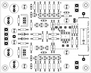
I added the package dimensions (1.1"x1.1")on the silkscreen to give you an idea of the size and position. The pads for the package are there, not labelled at the moment.
Verified the proof of concept.
Is the result basically what you had in mind?
To be honest, 1.1" is a tad small for a prototype board. The ability to try some of these DOA modules though does interest me.
Indeed, this was my line of thinking: the main advantage is a proper class A output stage at high output current, but this isn't going to be relevant for the Sapphire circuit, where the op amp is pretty much just a voltage amplifier - no current drive needed. The other stated advantage is the matched/low noise input transistors. Well, it might it might not: I'd like to hear for myself.
I keep an open mind about these things. Which part did you have in mind? The basic issues are power dissipation/current handling and availability in through-hole**/DIP packages.
**one of these days the economics of it will mean I'll probably have to sell pre-built SMT boards instead of kits. Through hole parts are disappearing, while SMT prototyping by Chinese fabs is becoming increasingly viable.
Verified the proof of concept.
Is the result basically what you had in mind?
To be honest, 1.1" is a tad small for a prototype board. The ability to try some of these DOA modules though does interest me.
A DOA will not be all that much better than a PDIP opamp in this application.
Indeed, this was my line of thinking: the main advantage is a proper class A output stage at high output current, but this isn't going to be relevant for the Sapphire circuit, where the op amp is pretty much just a voltage amplifier - no current drive needed. The other stated advantage is the matched/low noise input transistors. Well, it might it might not: I'd like to hear for myself.
If IC are good for front end, then wouldn't the new national current buffer be a worthwhile output stage?
I keep an open mind about these things. Which part did you have in mind? The basic issues are power dissipation/current handling and availability in through-hole**/DIP packages.
**one of these days the economics of it will mean I'll probably have to sell pre-built SMT boards instead of kits. Through hole parts are disappearing, while SMT prototyping by Chinese fabs is becoming increasingly viable.
Last edited:
Chinese pcb assembly houses will charge about one penny per smt lead, so 2cents per resistor/diode/cap. Certainly less fun to build and significant money invested before knowing how many you'll sell. Also trusting they will use the brands you wish rather than just Yageo resistors or whatever the house brand is...you probably won't get what you pay for.
Ran across this listing last night on the DIY Audio Wiki - discrete-opamps which lists most of the available ones, including one that fits in a 8-pin PDIP socket - Sparkoslabs.com.
From looking at the specs and such, that's probably all that is needed for $39 ea. It's not a FET, but does have the Class A output stage.
My other delusional thinking that has been flitting around in my brain since seeing the Sapphire 3's output stage was - gee it'd be nice to put that on a 2520 module using smt transistor pairs - 2 NPN and PNP per package, and leave the resistors as through hole. (The whole sort tiny packages by hfe and soldering them on...well, yeah that's an issue.)
That way, the "motherboard" would have the voltage regulators, 2 x 2520 footprints, a feedback network around the first that could be converted from a headphone amp to the VSPS, and the second device could be used with switching - breakout the connection between the two, for a pot - on the input for the headphone amp, of the buffer for a 0 db gain preamp.
To wrap it up, the layout looks fine! Given that Sparkos can provide what I'm looking for in an opamp, I'm fine with the Sapphire 3 as is. If you go ahead with the 2520 layout, I'm in for boards and will happily purchase them, if you decide not to, that's fine as well, I'll just build the kit I have.
Thanks!
I used to do that. Get samples I mean. I had a nice collection of "bugs".
But at the end of the day it's something like audio cables: yes different ones sound slightly different, but it's just not something I can get worked up over anymore. Pick an op amp suitable for the circuit application (which for the Sapphire is just about any "for audio" type) and call it a day.
Anyway I quite like the sound of the NE5534. Really! I find it perfectly acceptable, though I ship OPA134 with the Sapphire as the FET input is arguably a better fit to follow the volume control (the numbers come out pretty even, as the impedances are just on the BJT/FET crossover) I could sub the NE5534 back in I doubt any of you would notice. I doubt I would!
FWIW There is no particular reason the OPA627 should be better than the OPA134 in this application.
I added the package dimensions (1.1"x1.1")on the silkscreen to give you an idea of the size and position. The pads for the package are there, not labelled at the moment.
Verified the proof of concept.
Is the result basically what you had in mind?
To be honest, 1.1" is a tad small for a prototype board. The ability to try some of these DOA modules though does interest me.
Indeed, this was my line of thinking: the main advantage is a proper class A output stage at high output current, but this isn't going to be relevant for the Sapphire circuit, where the op amp is pretty much just a voltage amplifier - no current drive needed. The other stated advantage is the matched/low noise input transistors. Well, it might it might not: I'd like to hear for myself.
I keep an open mind about these things. Which part did you have in mind? The basic issues are power dissipation/current handling and availability in through-hole**/DIP packages.
**one of these days the economics of it will mean I'll probably have to sell pre-built SMT boards instead of kits. Through hole parts are disappearing, while SMT prototyping by Chinese fabs is becoming increasingly viable.
Buf634 I guess is getting a bit old, but wouldn't discard it, then maybe one of these?
LT1223 - 100MHz Current Feedback Amplifier - Linear Technology
http://www.ti.com/lit/ds/symlink/lme49600.pdf
Yes I know, its sad but true through hole is not long for this world. The guys over at headcase are constantly redesigning boards for available parts. I think BC50/560 will be available for at least 5 years. If you look out to ten it may be slim pickings.
I used to do that. Get samples I mean. I had a nice collection of "bugs".
But at the end of the day it's something like audio cables: yes different ones sound slightly different, but it's just not something I can get worked up over anymore. Pick an op amp suitable for the circuit application (which for the Sapphire is just about any "for audio" type) and call it a day.
Anyway I quite like the sound of the NE5534. Really! I find it perfectly acceptable, though I ship OPA134 with the Sapphire as the FET input is arguably a better fit to follow the volume control (the numbers come out pretty even, as the impedances are just on the BJT/FET crossover) I could sub the NE5534 back in I doubt any of you would notice. I doubt I would!
FWIW There is no particular reason the OPA627 should be better than the OPA134 in this application.
I'm starting to think this way too now. I used to think the Navguy or whoever started bagging audiophile chips was being provocative and almost trolling. I think now he may be more right than I gave credit. He is in good company with Douglas Self I believe. I think Doug self said most BB or TI chips are not great audio chips and since NE5534 only worthy or true successor is the new line of National chips, lme47910 being one of them. But this is not verbatim, and I think I read this comment on the forum from another member so cant be sure if its true.
I expect in a few years you will be able to fabricate the Sapphire in a chip and get a run of several hundred made at a pop, put it a board with PSU and I/O and job done. Check out Jeremy Rifkin zero margin cost society, pretty fascinating if things go as he predicts.
LT1223 is a diamond buffer / current mirror / diamond buffer circuit rated 6 mA total current, probably 2 mA at most in the output pair. LME49600 is a simple diamond buffer and maxes out at 13.2 mA total bias current, likely only half of that in the output. BUF634 is essentially the same circuit as the LME49600 but can run at 15 mA, again maybe as little as half that in the output.
None are able to provide significant power output to headphones without dropping out of class A. (Sapphire 3 is 30-35 mA in the output alone, and that is on the relatively light side. I would say 30-100 mA is desirable, depending on if you care to drive inefficient low impedance headphones or not.)
Douglas Self measured a bunch of op amps and concluded the NE5534 was as good as any for audio use, and a lot better than some. (required reading...) Keep in mind that these are distortion figures for a specific, largely ideal, test circuit. Change the input impedance or the gain, for example, and the overall picture could be expected to change, possibly dramatically.
There is also a part 1,2 and 4. Google.
Last edited:
LT1223 is a diamond buffer / current mirror / diamond buffer circuit rated 6 mA total current, probably 2 mA at most in the output pair. LME49600 is a simple diamond buffer and maxes out at 13.2 mA total bias current, likely only half of that in the output. BUF634 is essentially the same circuit as the LME49600 but can run at 15 mA, again maybe as little as half that in the output.
None are able to provide significant power output to headphones without dropping out of class A. (Sapphire 3 is 30-35 mA in the output alone, and that is on the relatively light side. I would say 30-100 mA is desirable, depending on if you care to drive inefficient low impedance headphones or not.)
Douglas Self measured a bunch of op amps and concluded the NE5534 was as good as any for audio use, and a lot better than some. (required reading...) Keep in mind that these are distortion figures for a specific, largely ideal, test circuit. Change the input impedance or the gain, for example, and the overall picture could be expected to change, possibly dramatically.
There is also a part 1,2 and 4. Google.
Clearly one of us has done their homework
Thanks for the link, I will give it a read.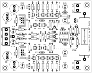
Sapphire 3.1m (Fab-ready, for final review.)
[Sapphire 3.1 is compatible with "2520" footprint discrete op amp modules.]
Custom wirepads to fit Mill-Max 344 pin receptacles.
Moved resistors near the IC to give better clearance around the pin receptacles.
Removed R27,R28 and C11,C12 from the schematic.
General nip-and-tuck for the traces.
Triple-checked 2520 outline and pin positions.
Attachments
Hi Richard,
I was thinking about another improvement that could be conisdered later on.
As we know not all Pre-Amps have a good phone amp, while the Diamond buffer in your amp is quite interesting.
So the thought is to make an optional switchable input to the Diamond buffer on the amp board, so that
1. It can be feeded from headphone amp
2. It could be feeded from a pre-amp
Allowing to build in this headphone amp in a pre amp unit, as a result you can get a good pre amp with great headphone amp functionality.
if the switch functionality is not used, the headphone amp can be directly connected to the Diamond buffer.
Do you think this is an interesting area to explore ?
Thanks for your comment.
So you want a switch to bypass the volume control and voltage amplifier parts the Sapphire? Is that right?
I am thinking of offering the buffer circuit of the Sapphire as a standalone board, possibly with voltage regulation but most likely without. Would that be of any interest? You could add it more conveniently to existing equipment like preamps, or mix or match power supplies and voltage amplification as you like. It could be set up as a line buffer or headphone driver, depending on the configuration.
Trying to put in a jumper/switch between the op amp and buffer is doable, but I'm not sure enough people would be interested to warrant the additional complication that everyone who didn't want to use the feature would now have to wire a shorting jumper.
1. It can be feeded from headphone amp
2. It could be feeded from a pre-amp
So you want a switch to bypass the volume control and voltage amplifier parts the Sapphire? Is that right?
I am thinking of offering the buffer circuit of the Sapphire as a standalone board, possibly with voltage regulation but most likely without. Would that be of any interest? You could add it more conveniently to existing equipment like preamps, or mix or match power supplies and voltage amplification as you like. It could be set up as a line buffer or headphone driver, depending on the configuration.
Trying to put in a jumper/switch between the op amp and buffer is doable, but I'm not sure enough people would be interested to warrant the additional complication that everyone who didn't want to use the feature would now have to wire a shorting jumper.
I am thinking of offering the buffer circuit of the Sapphire as a standalone board, possibly with voltage regulation but most likely without. Would that be of any interest?
It would be to me. I'm always interested in trying a different buffer.
Could a volume put be hung onto the front of it?
Thanks...
Could a volume put be hung onto the front of it?
Short answer: "Yes. It's a high impedance input."
Long answer: "No. The buffer provides current gain and load isolation for the op amp, but works best (as Patrick "EUVL" pointed out to me) when driven by a relatively low impedance source. The op amp in the Sapphire provides a constant, low impedance drive for the buffer in addition to providing the voltage gain. There is also a coupling cap and all the right impedance matching so things like the output offset voltage and distortion do not change with the position of the volume control."
It would require a fair bit of care and extra circuitry to get to the buffer to work properly, essentially duplicating what is already on the board to no good effect! If you don't need gain, set the op amp as a unit gain buffer (R4=short, R3=open circuit) and use the boards fully populated your "buffer".
The Sapphire is normally configured as a complete headphone amplifier - line input / volume control / voltage gain / current amplifier. As is, it is also a preamplifier. You'd add line input select, and a set of RCA jacks connected to the output, in parallel with the headphone jack (switched so its line or headphone drive but not both).
That's a cheat, though a common one these days: a preamplifier should formally have separate circuits for the line out and headphone out. Since its rare that people what to use both outputs simultaneously though, it's a luxury many can do without. Just be aware that the gain setting will be a bit of a compromise. A preamp usually has 6-12 dB voltage gain, while headphone amps vary more, from 0-28 dB. So what is perfect for your amp-speakers may be a little too much or too little for your headphones. This can be mitigated for low impedance headphones by increasing R21 to 47 ohms or something of that order, but if you want 28 dB for example to drive HD600s, it means it will be a bit too much as an ideal preamp, and a bit noisy as a result.
The solution is to use two sapphire boards, one for the preamp section and one for the headphone amplifier.
Yes, I have a fix for every problem.
- Home
- Amplifiers
- Headphone Systems
- RJM Audio Sapphire Desktop Headphone Amplifier