replacement of transformer
I have change the transformer with a 50VA 12v Rcore for 17€, now the temperature of the transformer is correct.
After two weeks, i'm satisfied ,but i found the high frequency a little bit hard
(my headphone is a Sennheiser HD600).
I can't test with my DAC because i have put it in my DIY préamp.
Has anyone find the same sound?
I think i'll be go to change some capacitor with better quality.
Wait and see...
If you still have all those horrid caps in there especially the ceramics that will make it sound hard>get rid of them Now!
The Alps BV pot will fit on the board if you fit a couple of components to the underside of the PCB which is very easily done.
Keep up the good work guys.
PS the most important caps are C1 (Input) and C4 (Feedback).
The Alps BV pot will fit on the board if you fit a couple of components to the underside of the PCB which is very easily done.
Keep up the good work guys.
PS the most important caps are C1 (Input) and C4 (Feedback).
Last edited:
Oh I just found this. 
I was referring to the original JLH schematic, Still a bit of confusion over the part numbers.
We should all stick to the JLH schematic The Class-A Amplifier Site - JLH Headphone Amplifiers
Unless Miles has redone it to include the power supply.
Hello all
A question for Hotiron : for reduce the gain, you said change R5 the value (470ohms)
my R5 value is 4.7K
I was referring to the original JLH schematic, Still a bit of confusion over the part numbers.
We should all stick to the JLH schematic The Class-A Amplifier Site - JLH Headphone Amplifiers
Unless Miles has redone it to include the power supply.
Replacement capacitors
Hello all:
Hotiron: excuse me for the two differents schématics, i have made a mistake.
MilesCampbell: i don't know if i can change only R9/R10 2.2K with 3.3K, what are their functions ?
Yesterday, i'have changed the two input capacitors with Muse BP 1μF (C1) and the two feedback with 470μF audio capacitors (C4).
The sound is better without a doubt.
I have replaced the horrible ceramics capacitors with Mkt (same value)
I think it's better to conserve all the 0.1μF but replaced with better ( Mkt) because it's always better for the highly frequencies.
Overall, i think it's a very good schématic but lot of components are bad.
It will be better to buy only the Pcb and solder good components.
Next stage is to replace the potentiometer.
Go on, we are on the right way!!
Finished mine - very nice so far, but a bit of 100Hz mains noise to deal with (suspect it's no more than ground routing inside the amp).
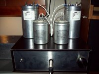
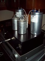
Didn't want to take any risks with my headphones, and had some 600uF polypropelene caps so went cap coupled on the output.
DC offset on output varied all over the place when the amp was first turned on. After a couple of rounds of adjustment the two channels are still varying with temperature (but now follow each other to a large extent).
Given that I have output coupling caps, is it best to adjust the DC offset to zero, or would it be advantageous to deliberately choose a few hundred millivolts?
Attachments
..........but i found the high frequency a little bit hard (my headphone is a Sennheiser HD600)....
This is a rather late response !
I have a HD 580. There is no problem with the sound. Surely doesn't sound hard at HF or mid frequencies. Sounds great.
Did you do an A/B comparison with another amp ? If this was true you would easily notice it in an A/B comparison. Needless to say levels have to be matched accurately.
Hello Ashok
After having listened lot of music, i'm thinking that is a very good headphones.
For the high frequencies, i was wrong, it's because spectrum is more balanced.
The only other headphones i have listened is my pc soundcard with an AKM 4396 and good Opamp, the JLH sound better just with an analogic output of mY Marantz CD6000.
Absolutely no noise, just the potentiometer at the beginning: i only ear a right way.
I'm going to change it one of these days.
The only problem is when you're change the headphones or try to use as preamp (great sound, with incredible clarity)because the offset change.
I have found a schématic with an opamp for have a null offset.
I think it's a good way, but for the moment,I continue to listen with my HD600 because I'm not a specialist of printed circuit board
I heard the HD600 at the Canjam at the RMAF last week. I think the 600 is better than the 580. So your phones are good.
On my JLH headphone amp with split supplies ( +/- 12 V supplies ) I have very low offset. less than 1 mV and it is quite stable. This will also depend on how big your heatsink is. If it dissipates the heat well the drift will be minimised. Surprisingly the amp sounds very good even with very low bias current in the output .
If you really want protection a capacitor is an easy way out but the cap almost certainly will affect the sound. You can use a relay with an opamp to sense the dc. That will overcome the capacitor problem.
Hey Everyone, hope you're enjoying the holidays.
Holidays = DIY audio (even with my 14 month old son!)
First, I'd like to thank Miles on behalf of everyone for his great step-by-step assembly instructions. Great pics and testing!
Because of my lack of time, I decided to go the easier route and ordered an assembled board from:
JHL Class A headphone amplifier pre-amp preamplifier kit diy | eBay
It's the green PCB and the soldering looks pretty good. It came with standoffs, volume knob and a header and crimps for the input connector. Plug-and-Play, baby! The seller seems nice and I even got a Christmas Card!
As previously stated, the feedback caps C23 and C24 were backwards (reference to the sellers .pdf schematic a few pages back) and I replaced them with some Pan FM 150uF.
The volume pot was a B10k (which is linear) and combined with the high gain made for a twitchy volume control. I replaced it with a series stepped attenuator I got from from Gigawork. It fit but I had to remove an input cap and then re-solder it.
The DC offset does drift. When you first power up its ~100mV, but within 10 minutes it's down to ~10mV and then ~3mV after 30 minutes.
For giggles I hooked it up to some ... speakers! I'm listening to some Tool as I type this on bookshelf speakers flanking my computer. Good for low to medium listening but runs out of steam and distorts when you crank it. Not bad for a headphone amp!
The gain's still a bit high for headphones. The gain is set by resistors R12 (1k) and R17 (470), correct? Looks like most people are increasing R17 to lower the gain. Could you instead decrease R12 or is R12 also involved in other parameters of the circuit as well?
I'll be comparing it to some other headphone amps over the next few months.
Cheers,
Jeff
Uh... shouldn't a 'B' pot be log ('A' is lin)?
Anyway... if you look at the original circuit 1, you'll find that audio gain is set by R7 (4k7) and R5 (470). Q4's quiescent current passes through R7, hence changing that would immediately upset output DC offset. That's why people prefer increasing R5 instead. (Not sure of stability implications, but it seems to work.) These single-ended inputs are a bit tricky to work with.
This was a good design in its day. Well-behaved distortion, low output impedance. It's not exactly a low-noise or PSRR champ though. Without the ability to transition into Class AB, it's not the best for experiments in driving speakers either.
i found it..
It was a 0 ohm resistor ,that broke somehow ,replaced and did all the tweaks
but with 470uF feedback caps (next to 1Uf ones )i get a small buzz (but otherwise much better, volume turned half way...
It almost dissapears with a resistor from one of the tip41 heatsink to ground ,is there another way to compensate ?
.... my 0.1 are in place
[*]Replace the Zener Diode with 3 x 1N4148 in series (6 off) - Note the polarity is opposite to that of the zener.
Can you please explain this more exactly? I should instead of the zener diode use three 4148 and put them in series?
Cause on the photo of the pcb I see only one diode...
Stage 2
With a small number of replacement components the design takes another step forward. Using picture 3 as our guide
Implement Stage 1
Change 2k2 for 3k3 resistors (2 off)
Remove the two 10k variable resistors and link as required
Replace 4k7 with 10k (2 off)
Replace 220k with 47k (2 off)
Replace the Zener Diode with 3 x 1N4148 in series (6 off) - Note the polarity is opposite to that of the zener.
Which 4k7 shall I exchange, there are quite a few...
- Home
- Amplifiers
- Headphone Systems
- JLH Headphone Amp