Step 5 and 6 Resistors and rectifier diodes II
Picture List
Comments
Tip : Please double check the 1N4007 direction
Picture List
- Rectifier Diodes and LED
Comments
- The 1N4007 has a sliver band which denotes the cathode and this band can also be found on the PCB,
- It is VERY important the 1N4007 are fitted the correct way around in the PCB
- The LED has a very tiny flat on the side of the round case with a longer leg this again denotes the cathode. This is the - or negative connection of the LED.
Tip : Please double check the 1N4007 direction
Attachments
Step by Step....
Miles, this SbS is so good even a newbie like myself is (so far) having no trouble at all. Diodes are in, resistors are in, and as my workbench is also my office I've put the heatseaks on so it sits on the bench and there's no hot stuff resting on the bench. Looking forward to the next installment...")
Miles, this SbS is so good even a newbie like myself is (so far) having no trouble at all. Diodes are in, resistors are in, and as my workbench is also my office I've put the heatseaks on so it sits on the bench and there's no hot stuff resting on the bench. Looking forward to the next installment...
Errrmmmmmmm Right ho !!
Hello Steve
I have to admit that I didn't think anyone would be interested..
It's kind of my own journey into JLH and his designs ..
So I'd better get on with the next installment
Thank you very much for your feedback
Miles
p.s. I'm a bit worried about having the heatsinks on already, but let see how we go ..
p.p.s. Pattie in a Bread cake, oooowwww how I miss them I really enjoyed my time in Hull ..
Hello Steve
I have to admit that I didn't think anyone would be interested..
It's kind of my own journey into JLH and his designs ..
So I'd better get on with the next installment
Thank you very much for your feedback
Miles
p.s. I'm a bit worried about having the heatsinks on already, but let see how we go ..
p.p.s. Pattie in a Bread cake, oooowwww how I miss them
I really enjoyed my time in Hull ..Yay! Bread Cakes...
If you only knew how many arguments my girlfriend and I have had.. Her being a Geordie, bread cakes are bread 'buns', patties as I know them don't exist, and a hundred and one other differences! English as a common language.. HA!
PS When were you in Hull? Things don't change much around here...
Steve.
JHL kit amplifier
I think the journey you're on is an interesting one. For me, it's a learning process for my next kit, a PANDA headphone amplifier. Saying that, I may prefer the JHL, at which point I may well follow you further, and pass the PANDA to my girlfriend's son. He's looking for a good amp, so whatever happens I think he's on to a winner. When I do things I always mean to document things, but then I start and... well, you can guess
I'm still finding cables from my home and office rewire, and wonder where the other end is
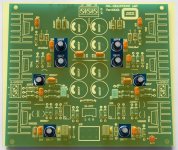
Step 8 Capacitors
Picture List
Comments
Tip : Solder ONE leg of a capacitor first. Then re-melt that soldered leg pushing the cap against the board. This makes sure the capacitor doesn't wobble .. Then proceed to solder the other leg in the normal manner.
Picture List
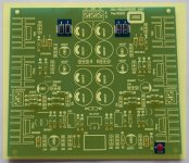
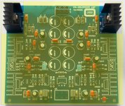
- Capacitor 330pF - 2 off
- Capacitor 0.1uF - 14 off
- Capacitor 220pF - 14 off
- Capacitor 470nF - 2 off
- Capacitor 100uF - 8 off BEWARE OF POLARITY
Comments
- I would strongly suggest that the build order above is followed, otherwise the small capacitors would become a real pain to fit.
- Either side of the potentiometer the board requires a capacitor of the value 105 which is shorthand for 10^5 or 1uF or 1000nF or 1,000 000pF These are NOT included in the kit of parts but 0.47uF or 470nF I believe has been substituted.
- The 100uF capacitors are marked on one side with a minus sign and a shorter leg. The PCB is marked with a smile and this is the negative leg.
- Failure to insert any electrolytic capacitor with the correct polarity can lead to CATASTROPHIC consequences.
Tip : Solder ONE leg of a capacitor first. Then re-melt that soldered leg pushing the cap against the board. This makes sure the capacitor doesn't wobble .. Then proceed to solder the other leg in the normal manner.
Attachments
I think the journey you're on is an interesting one. For me, it's a learning process for my next kit, a PANDA headphone amplifier. Saying that, I may prefer the JHL, at which point I may well follow you further, and pass the PANDA to my girlfriend's son. He's looking for a good amp, so whatever happens I think he's on to a winner. When I do things I always mean to document things, but then I start and... well, you can guess
I'm still finding cables from my home and office rewire, and wonder where the other end is
Hello Steve
The Deep had just been started when I left after a wonderful 5 years there .. Is Spiders still there ??
Now the panda is an interesting beast ... Reading the extensive threads, there is not much to add. Was this another ebay purchase?
Right that's enough for one day
Miles
Spiders and Pandas
The Panda was an ebay purchase, it's due in a week or three. Should be a fun second project. Hopefully I'll learn something from the JLH and Panda threads and your geat SbS will help too. I've recently rebuit my Beyer DT990s and need a good amplifier.
Spiders will be there when the sun flickers and goes out. I know it's been going for at least 30 years, and is still the same (so I'm told by those young or strange enough to go).
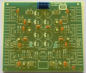
Step 9, 10, 11 and 12 The Power supply
Picture List
Comments
Tips
Next the power supply of the board needs to be tested.
Picture List
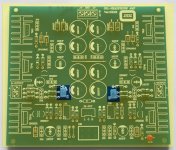
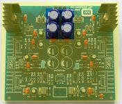
- Vin Connector
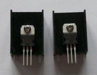
- Voltage Regulators assembled on to heasinks (See tips)
- Voltage Regulators mounted onto the PCB (See tips)
- Capacitors - Smoothing 2200uf 4off (Pre-Regulator) BEWARE OF POLARITY
Comments
- There is a slight misalignment between voltage regulator and the heatsink alignment holes on the PCB. The regulator pins are not quite straight when all is complete.
- The 2200uF capacitors are marked on one side with a minus sign and a shorter leg. The PCB is marked with a smile and this is the negative leg.
- Failure to insert any electrolytic capacitor with the correct polarity can lead to CATASTROPHIC consequences.
- The voltage regulator part numbers are very similar, 7912 and 7812 care is required at this stage. The 7912 is require for the negative -12V supply and mounted to the left of the board as shown with VIn at the top. To the right is 7812 which is the positive +12V supply.
Tips
- Soldering the Vin connector it is very easy to have a gap UNDER the connector to the board. Simple trick is to solder the centre pin of the connector first, check to see if the connector is flush to the PCB and solder the outer two legs..
- Can I suggets that the voltage regulators are mounted onto the heatsinks with the screws LOOSE...
- Solder the middle pin of the regulator first, then check to see if the assembly is mounted square and flat to the PCB. Now solder the other legs of the regulator and the heatsink. Finally tighten the screw on the heatsink.
- The large power supply smoothing capacitors are another component which it can be easy to leave a gap between to the PCB. Again solder one leg and check that the component is tight to the PCB.
PCB = Printed Circuit Board
VReg = Voltage Regulator
Next the power supply of the board needs to be tested.
Attachments
Almost there...
I've checked the PSU, and got 12v and -12v to within a sufficient tiny margin. I'm using a 15-0-15v AC 30VA transformer, as I had it to hand, for a pre-regulator voltage of +/- 22v DC.
I've populated the board fully, and attached a 270R 2w resistor to each output for testing. The board has been gone over three times with a magnifying glass, and potentially dodgy joints redone.
So, I'm ready to fire up.
I'm guessing the pots are for DC offset, and should be adjusted for lowest output, then readjusted a few times during the first few hours of running. I'll start with them in the middle position, and adjust from there.
Fingers crossed! (Makes it difficult to handle meter probes though..)
Steve
Hello
I have just finished and tested my headphone amp with my HD600 ' after controls of course), it works fine but the level is too high.
where are the resistors to change to reduce the gain?
Thanks
You need to increase the value of R5 (470R) to reduce gain I have 2K2 in place which is good for my Senheiser cans HD 565s.
I seem to build very S L O W L Y ..
Hello all
Sorry for the delay but I seem to build and document very slowly..
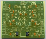
Picture List
fj12centauro
I have to admit using TIP41 in the output stage my assumption was there may not be enough gain! Which type of source are you all driving from ?
hotiron
Thanks very much I will try that. On the Chinese Version it's R17 and R18 that can be found in the first picture below..
All
Attention must be draw to C23, C24 it has been highlighted on the composite image attached. The PCB and the schematic both show it the incorrect polarity!! Electrolytic capacitors are very sensitive to incorrect polarity so can I suggest this is replaced and a new one is insert with the corrected the polarity ..
This week I will try and catch up with you guys and get the testing done.
Hope this helps
Miles
Hello all
Sorry for the delay but I seem to build and document very slowly..
Picture List
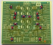
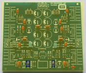
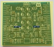
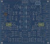
- R17, R18 470 ohm resistor
- Composite board image highlighting C23, C24
fj12centauro
I have to admit using TIP41 in the output stage my assumption was there may not be enough gain! Which type of source are you all driving from ?
hotiron
Thanks very much I will try that. On the Chinese Version it's R17 and R18 that can be found in the first picture below..
All
Attention must be draw to C23, C24 it has been highlighted on the composite image attached. The PCB and the schematic both show it the incorrect polarity!! Electrolytic capacitors are very sensitive to incorrect polarity so can I suggest this is replaced and a new one is insert with the corrected the polarity ..
This week I will try and catch up with you guys and get the testing done.
Hope this helps
Miles
Attachments
Last edited:
Sorry bout that Miles I was referring to the JLH schematic.
The Class-A Amplifier Site - JLH Headphone Amplifiers
The Class-A Amplifier Site - JLH Headphone Amplifiers
This is a VERY good point ...
Hotiron, this is a VERY good point you have mentioned
Quite frankly the provided schematic is AWFUL and the part numbering is all over the place and it's on the list to be redone. This is the first build of 4 different types, and is a learning exercise for me with a bunch of new toys and a subject which I have messed with since being a young lad moving then onto my first degree ..
Please keep the comments coming, they are really helpful ..
Thank you
Miles
Sorry bout that Miles I was referring to the JLH schematic.
The Class-A Amplifier Site - JLH Headphone Amplifiers
Hotiron, this is a VERY good point you have mentioned
Quite frankly the provided schematic is AWFUL and the part numbering is all over the place and it's on the list to be redone. This is the first build of 4 different types, and is a learning exercise for me with a bunch of new toys and a subject which I have messed with since being a young lad moving then onto my first degree ..
Please keep the comments coming, they are really helpful ..
Thank you
Miles
Modify the gain
Hotiron : Thanks, for your answer, i'm going to try some different value.
MilesCampbell: I use a Marantz CD6000 with discrete Opa Moon in the output
Very good sound!
it's a very good idea to post you build
Other questions:
Is someone replace the original potentiometer with an ALPS Blue Velvet?
I'm looking on ebay for a output protection, what are you think about?
Because i pull on my JLH, after ten minutes i plug my headphones and the offset don't move, the value is around 3 millivolts.
More great questions
Very nice CD player setup
Good idea to change potentiometer, for the next build attempt to change to Alps Blue Velvet.
I will put one on the next order.
Protection and offset : Can I will answer by the end of the week ?
Steve : Did you manage to get the offset to zero ?
Great conversation guys,
thanks Miles
MilesCampbell: I use a Marantz CD6000 with discrete Opa Moon in the output
Very good sound!
it's a very good idea to post you build
Other questions:
Is someone replace the original potentiometer with an ALPS Blue Velvet?
I'm looking on ebay for a output protection, what are you think about?
Because i pull on my JLH, after ten minutes i plug my headphones and the offset don't move, the value is around 3 millivolts.
Very nice CD player setup
Good idea to change potentiometer, for the next build attempt to change to Alps Blue Velvet.
I will put one on the next order.
Protection and offset : Can I will answer by the end of the week ?
Steve : Did you manage to get the offset to zero ?
Great conversation guys,
thanks Miles
output protection
Yes of course , i'll be wait, i'm a little afraid because i don't want destroyed my precious headphones.
I just see that my transformer is very hot, it's make 20VA, perhaps it's too small. what are the power of you transformer?
The problem of the offset is when the temperature goes up, the offset goes down.
Perhaps the right and cheaper way will be to have only one big heatsink for the four TIP, what are you think about?
Excuse me for my bad english, but you're know that frenchies only talk french
best regards from a french biker with a modest 600 Transalp
Yes of course , i'll be wait, i'm a little afraid because i don't want destroyed my precious headphones.
I just see that my transformer is very hot, it's make 20VA, perhaps it's too small. what are the power of you transformer?
The problem of the offset is when the temperature goes up, the offset goes down.
Perhaps the right and cheaper way will be to have only one big heatsink for the four TIP, what are you think about?
Excuse me for my bad english, but you're know that frenchies only talk french
best regards from a
french biker with a modest 600 TransalpRe: Offset
I need to grab a couple of 100uf and get them fitted first... I compared the original JLH schematic and the JHL version, and as you say the cap is the wrong way round. Damn. Never mind..
If I get the unit running, I have a 50K alps blue I salvaged from an old dead CD player. I might use that. Let's walk before running first
fj12centauro : Your english is very good, don't worry can I suggest writing lots of words similar to what you mean in (brackets) and we can help .. The heatsink that are used on this PCB can be stacked or replaced with a taller version, I'll find a picture ...
badgerboy : I'm very interested in the fit of the Alps on the pcb
General Note : Can I strongly suggest that a CHEAP pair of headphones is used at this stage for testing ..
To Done List
This week should see the finish of the power supply testing and the SbS build.
Thank you for all your comments, keep them coming ..
Miles
badgerboy : I'm very interested in the fit of the Alps on the pcb
General Note : Can I strongly suggest that a CHEAP pair of headphones is used at this stage for testing ..
To Done List
- Will Alps Blue Velvet fit the PCB ?
- Is an output protection module required ?
- What is a sensible transformer specification ?
- Draw a logical and simple schematic
This week should see the finish of the power supply testing and the SbS build.
Thank you for all your comments, keep them coming ..
Miles
Last edited:
- Home
- Amplifiers
- Headphone Systems
- JLH Headphone Amp