Sheesh that's cheap! I will have a look. Have you built a LM3886 also?
So is matching impedance between the preamp and power amp as simple as matching with headphones--i.e. coupling with enough capacitance to ensure bass response?
There is no impedance matching issue. Most chipamps have a 10k to 100k input impedance. The PCA can drive 60ohm impedance if needed, so 10k is nothing.
Chip amps are cheap indeed - good ones with nice components will run you about $40.
I have pre-built LM3886's, but not built it myself, no point when they are so inexpensive fully-built. I have one just like this (without the HS it was $40. It sounds quite decent and has ability to change out input opamp stage).
NEW LM3886 Full DC servo Redux Immersion Gold Process 68W+68W 5534 independent op amp amplifier finished board with heatsink-in Amplifier from Consumer Electronics on Aliexpress.com | Alibaba Group
This looks nice too and has output Thiele network (inductor).
NOVER LM3886 NE5532 HIFI audio amplifier board stereo 2.0 channel hifi amplifier 68W * 2 CG version LM3886 power amplifier board-in Amplifier from Consumer Electronics on Aliexpress.com | Alibaba Group
Last edited:
Nice. If impedance doesn't matter, maybe it is just a matter of "synergy." Have you paired a PCA with your LM3886 before?
My goal would be to couple the preamp with the amp using a single PP or PPS film cap if possible. If the cap is preferred near the load, I guess that would dictate that I should leave the output cap off of the PCA board and just have a film on the input of my amp.
My goal would be to couple the preamp with the amp using a single PP or PPS film cap if possible. If the cap is preferred near the load, I guess that would dictate that I should leave the output cap off of the PCA board and just have a film on the input of my amp.
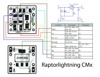
Trying to get started on the Raptorlightning Cap Mx for my amp. The words printed onto my OSH Park PCBs are absoluetly tiny and hard for me to read. That, plus the fact that one pair of pads isn't labeled, led me to make this little assembly roadmap. I believe the unlabeled pads are for R2.
I tried to deduce the positive and negative pads for the 100uF cap as well, by looking at the board design and the schematic, and I labeled those in the image. This is important for me, as I am using a polarized electrolytic cap here and I don't want to blow it up. Noob alert.
Buzz, Raptor, or X, can you confirm that I got the polarity right?
Attachments
I am offering free shipping in continental U.S. on Nov. 11 (Eleven-Eleven sale) for 1-day only on all items in my shop.
I was going to say I still see a shipping cost, but then I realized its only the 10th

I thought it just gave me free shipping? At least I hope so lol
You got free shipping.
hey randy, I have a bunch, but I'm in Aus. Can send for price of postage - but from what raptor said sounds like in the US it may be cheaper for you just to order your own from oshpark.
thanks for the offer, but you're probably right, shipping will probably make it not work.
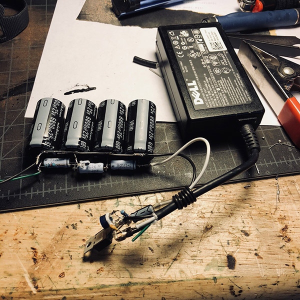
Hoping to make a CRCRCRC soon. Aatto, I was looking at the photo you posted of yours. I can tell you have three identical resistors soldered between the positive cap terminals. But then there is something else down there crossing over to the negative side...hard to tell from the photo...is that just a tiny resistor in series with a LED to serve as your power indicator? Just making sure I'm not missing something important.
Hoping to make a CRCRCRC soon. Aatto, I was looking at the photo you posted of yours. I can tell you have three identical resistors soldered between the positive cap terminals. But then there is something else down there crossing over to the negative side...hard to tell from the photo...is that just a tiny resistor in series with a LED to serve as your power indicator? Just making sure I'm not missing something important.
Looks like a 1k in series with LED for power indicator. 1k is a bit too small for my taste as that is 19mA at 19v. About 12k to 15k is a few mA, still plenty to give light and not burn out the LED prematurely.
you got it, was just a test run LED, already removed it .
Lol you have eagle eyes!
Brown Black Black Red Brown on Blue casing = 1k 1% metal thin film
One time, a member took a photo of his speaker in his study and posted it without thinking. From the minute details in the photo, I was able to deduce the books he was currently reading, the type of wine he was drinking, and the fact that he had a lady friend drinking in the room with him at the same time.
 Detective X
- Home
- Group Buys
- xrk971 Pocket Class A Headamp GB