thanks for replying metalman
Firstly I realised that i forgot to mention in my 1st post that i am using 3.01 ohm resistors for R10, R11, R12. these are what Digi01 supplied in his kit. I know that if i use 2.2 ohm that the bias would be higher but still not high enough to reach 300mA.
The reason behind me thinking that something was wrong with the circuit was that it did not reach 300mA which is what i though it was capable of and I couldnt balance the Id of Q1 and Q2.
R4 = 1.2
R16 = 6.9
R3 = 0.05
R10 = 0.59
R16 is a variable 100k set at its maximum resistance.
Thankyou
Mark
Mark,
OK, I checked your measurements in more detail, and the good new is that your headphone amp is working exactly as it should. With the parts you have in the circuit at present, the max possible bias is what you are measuring (i.e. ~200mA). Without changin parts, it won't go any higher.
For measurements to determine the contribution of the active current source, you want to measure the AC voltage contribution across R10 and R11, and adjust until the reading across R10 is one half of the value you read across R11. Seeing no AC signal across R12 is normal. By my rough check you appear to be pretty close to the optimal adjustment as you have things set right now.
Now, although I am running amp at 300mA bias, I am doing it solely on the basis that Nelson's general statement is that more bias is better. This amp will sound really good at 200mA, and pushing it to 300mA starts to push the thermal limits of the IRF610's, affecting long-term reliability unless you have them really well heatsinked. While I notice a difference in sound quality on my amp between 200 and 300mA bais, the difference is only distinguishable on certain very well recorded pieces of music. So if you want to stop where you are, you won't be missing much if anything.
That being said, if you are determined to run at 300mA bias, there are two ways to do it. First, If you can live without having a bias adjustment (this is more or less how I have my amp set up):
1) Replace R10, 11 and 12 with 2.2ohm resistors.
2) Remove R4 and 16 from the circuit.
3) Add a capacitor of ~1nF bridging the base and collector terminals of Q3 (this is necessary to stabilize Q1/Q3).
If you want to keep the bias adjustment, simply replace R10, 11 and 12 with 2 ohm resistors. This should give you a max adjustable bias of 300mA. In this case you don't need the extra capacitor as R4/R16 stabilize the circuit.
Hope this helps you out.
Terry
Thanks for the excellent reply Terry.
I have another of these amps built on stripboard that i can experiment on so i will probably try everything you suggested to to see if it does make a bit of a difference to me.
Do you have any details on the power supply that you are using for you amp, i found your schematic for it in your thread about your zen head amp.
Does it give better sound quality than a standard PS with caps or a CRC?
thanks a lot for you help
Mark
Mark,
My Power supply is a single transformer, followed by a CRC filter. The output from the CRC filter splits to two voltage regulators, one for each channel, each regulator followed by another filter cap (I think around 5600uf).
What affect did that have on the sound?:
The soundstage, which was already very good, snapped into tight focus. Most people say you can't achieve this with headphones, but to me I can sense the space of the recording room with nice relief of the front to back position of the sounds. Secondly, and I think this is because of the the better soundstage retrieval, I suddenly started hearing subtle little details in recordings that I had never heard before. I should mention here that to get this also involved bypassing each of C3, 4 and 5 with a 0.1uF MultiCap. I haven't tried replacing C3,4,5 with Blackgates, but some people I have talked to say they get the same effect too.
The only downside of using my (actually Nelsons) regulation stage in the power supply is that you loose 7-8 volts, and therefore have to change some resistors values in the circuit to get everything propoerly balanced. If you find yourself wanting to do this let me know and I will help you get it sorted out.
Cheers,
Doh!
Im still not able to adjust this current balancing thingy.
This is what im doing.
set o'scope to ac, apply 1kHz to amp, place probe across either R10 or R11, output is a big mess on the screen.
another thing that i tried.
set o'scope to ac, apply 1kHz to amp, place probe at node between R10/Q1 source and the probe ground to circuit ground, result is nice sine wave, adjusting R17 does nothing.
The same thing happens with R11.
Am I doing something wrong?
Thanks again
Mark
Mark,
Sorry I didn't respond sooner, I was on vacation. I am also sorry to hear about your measurement problem. Unfortunately I don't own or use an oscilloscope myself, I rely on the good graces of some of my co-workers who do measurements for me. But I will ask them their opinion and see if I can give you some feedback.
Terry
On the other hand, maybe some of the more experienced members here might chip in ... (blatant plug for others participation) ...
Update:
I have been listening to music through the amp and it sounds quite good without being run in.
I replaced my 3.01 ohm resistors with my old 2.2 ohm ones from my old amp and now get roughly (from memory) 260mA which is high enough with the heatsinks I have.
still cant figure out that current sharing thing
Thanks
Mark
Kram said:Update:
I have been listening to music through the amp and it sounds quite good without being run in.
I replaced my 3.01 ohm resistors with my old 2.2 ohm ones from my old amp and now get roughly (from memory) 260mA which is high enough with the heatsinks I have.
still cant figure out that current sharing thing
Thanks
Mark
Well done,Kram.
congratulations
BTW,the 4 of 3.01ohm resistors that I supply in the kit is high quality CGW brand.R10 and R12 should be match,then you can get stable DC points.
what headphone do you using?if it is a middle Z or high Z headphone,you don't need to charge the higher current setup, even if at least 100mA bias current is advisable for the best sound quality.
enjoys
digi
tschrama said:Any pcb boards left to buy?
greetZ,
Thijs
I have some boards available,but not kit supply.
net block ~
here is my parts list:
amp unit
R1\R2\R3\R8=1K,1/4W
R5\R6=220 ohm,1/4W
R7=33K,1/4W
R9=220K,1/4W
R10\R11\R12=3.01 ohm,1W 1%
R13=100K,1/4W
R14=180K,1/4W
R15=470 ohm,1/4W
R18=5.6 ohm ,3W
C1\C3=100uf/35V,ELNA CERAFINE
C2=4.7uf/63V,elna for audio Bp
C4\C5=470uf/63v,ELNA silmic
C6=2200uf/50v, ELNA Standard Audio Grade
TRIM R16=100K,R17=1K
Q1\Q2=IRF610,
Q3=2SC1815
power unit,a regulator power supply,22VDC for 2 channel.
LINK
ZANG
~here is my parts list:
amp unit
R1\R2\R3\R8=1K,1/4W
R5\R6=220 ohm,1/4W
R7=33K,1/4W
R9=220K,1/4W
R10\R11\R12=3.01 ohm,1W 1%
R13=100K,1/4W
R14=180K,1/4W
R15=470 ohm,1/4W
R18=5.6 ohm ,3W
C1\C3=100uf/35V,ELNA CERAFINE
C2=4.7uf/63V,elna for audio Bp
C4\C5=470uf/63v,ELNA silmic
C6=2200uf/50v, ELNA Standard Audio Grade
TRIM R16=100K,R17=1K
Q1\Q2=IRF610,
Q3=2SC1815
power unit,a regulator power supply,22VDC for 2 channel.
LINK
ZANG
Banned
Joined 2002
Ordered these:
Item # - Description Quantity Price Total
ROA103-ELNA 100uf/35V 4 1.10 4.40
ROA474-ELNA 470uf/63V 2 4.20 8.40
NICH23-NICHICON 2200uf/50V 2 2.05 4.10
V4-1.0k-Vishay/Dale 1/2 watt metal film 1.0kohms 10 0.20 2.00
V4-221-Vishay/dale 1/2 watt metal film 221 ohms 4 0.20 0.80
V4-33.2k-Vishay/Dale V4 1/2 watt metal film 33.2kohms 2 0.20 0.40
V4-221k-Vishay/Dale V4 1/2 watt metal film 221kohms 2 0.20 0.40
V4-20.0k-Vishay/Dale 1/2 watt metal film 20.0kohms 2 0.20 0.40
V4-100k-Vishay/Dale 1/2 watt metal film 100kohms 2 0.20 0.40
V4-1.82k-Vishay/Dale V4 1/2 watt metal film 1.82kohms 2 0.20 0.40
V4-475-Vishay/Dale V4 1/2 watt metal film 475 ohms 2 0.20 0.40
22.10
Zang- I did not find an ELNA 4.7uf/63 cap at Welborne labs. You know of another place to get it and theses: Now I need Q1/2/3, R10/11/16/17 & 18.
have you try http://www.mouser.com/ ?
Q1/2
Mouser Part #: 512-IRF610B 1: $0.460
Q3
Mouser Part #: 512-BC546B ,Cross reference match for 2sc1815
1: $0.240
R10\R11\R12
Mouser Part #: 261-1.0 1: $0.130 (no good)
4.7uf/63v
alternative
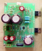
here is my board assembly photo:
Q1/2
Mouser Part #: 512-IRF610B 1: $0.460
Q3
Mouser Part #: 512-BC546B ,Cross reference match for 2sc1815
1: $0.240
R10\R11\R12
Mouser Part #: 261-1.0 1: $0.130 (no good)
4.7uf/63v
alternative
here is my board assembly photo:
Attachments
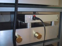
Just finished minehello everyone,have you finished your amp?
As it happened, I had a chassis like Tortello himself I fitted a heatsink in the bottom of it. It is running from a "pure breed" Zen regulator. Big caps are Black Gate's, input cap is a BC 4,7uF MKT. The sound is amazing I didnt use a pot for it, but runs the amp from my beloved BosoZ. I also had some rather tall feet machined for the chassis, to help the airflow around the heatsink. You can see the heatsink right underneath.The amp is totally quiet in the headphones, with no signal. Only a little "mosfet hiss", with the volume at full throttle.
Thanks, Tortello for this fine circuit, and DIGI01 for the boards
Steen
Attachments
steenoe-
I love the chassis.
Couple of questions:
1. Where did you get the chassis?
2. Why the heatsinks? Was the chassis it's self not enough to cool the amps?
I hope to finish mine soon, but I have been busy on my Krell Clone, Pass Mini-A, Hypex UcD-180's and the speakers all of them will be tried / used on...
I will try to post a picture of mine shortly. I have a chassis from Par-metal that will house a remote controlled input selector and volume control from DIYCLUB.biz, Pavels "audio refiner" (line stage) circuits, and a switch to go between Zangs headphone amp and BrianGT's LM3886 GC.
Although I may NOT implement Pavels circuit and save for a purist approach preamp later.
- Status
- This old topic is closed. If you want to reopen this topic, contact a moderator using the "Report Post" button.
- Home
- Group Buys
- New MINI ZEN Headphone Amp PCB group order...