We didn´t make comparsions.
I had it connected to the "Ceasar 2 & Cleo 6" of my friend John Eekels in an separate listening room.
Bas made a few pictures. Perhaps he will upload them in the gallery.
What did Doede say about your problem?
I had it connected to the "Ceasar 2 & Cleo 6" of my friend John Eekels in an separate listening room.
Bas made a few pictures. Perhaps he will upload them in the gallery.
What did Doede say about your problem?
Doede pointed out I had forgotten a wirebridge and had the cinch wired incorrectly, so I corrected that.
Unfortunately though, it didnt help... I am still soundless... even tried bypassing dem-reclock and i2s attenuator completely by wiring i2s (almost) directly to the tda.
Arrrgh! Running out of ideas
Unfortunately though, it didnt help... I am still soundless... even tried bypassing dem-reclock and i2s attenuator completely by wiring i2s (almost) directly to the tda.
Arrrgh! Running out of ideas

Got myself a scope, and started measuring around. I have measured the output of the dac using a 75ohm resistor to gnd.
Some preliminary findings:
- With DD's SPDIF board connected before the attenuator, there is no output on the dac
- There is also no output if I put the buffer in between
- If I connect the SPDIF board after the attenuator (no buffer), I get some output on the dac, namely quite some noise (but this could very well be the -2ma) idle current when the CD is on pause.
- and I do see some heavily distorted movements as a cd is playing, more or less with the music (it is really so distorted I couldnt even make out a clean sinus wave from a CD wave on the scope).
If I hadnt bought the TDA's from Cusackmusic (where others have bought ligitimate chips) and if I hadnt had 4 of these all displaying the same problem, I would have thought the chip is busted.
Would the above (especially bullet 4) be normal behaviour? So much noise with a 75ohm resistor? Or is it caused by some sort of impedance of the scope on the chip?
Got myself a scope, and started measuring around. I have measured the output of the dac using a 75ohm resistor to gnd.
Some preliminary findings:
- With DD's SPDIF board connected before the attenuator, there is no output on the dac
- There is also no output if I put the buffer in between
- If I connect the SPDIF board after the attenuator (no buffer), I get some output on the dac, namely quite some noise (but this could very well be the -2ma) idle current when the CD is on pause.
- and I do see some heavily distorted movements as a cd is playing, more or less with the music (it is really so distorted I couldnt even make out a clean sinus wave from a CD wave on the scope).
If I hadnt bought the TDA's from Cusackmusic (where others have bought ligitimate chips) and if I hadnt had 4 of these all displaying the same problem, I would have thought the chip is busted.
Would the above (especially bullet 4) be normal behaviour? So much noise with a 75ohm resistor? Or is it caused by some sort of impedance of the scope on the chip?
I think we should test the DD SPDIF and your DAC module in my DAC.
Therefore i invite you to come to me. Here we could search and look to your problem best.
Best,
Oliver
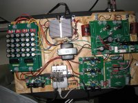
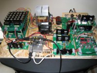
Finished!
Finally finished the build last night....
All voltages adjusted well and the sound is magnificent! I had forgotten how much I enjoyed the sound of the TDA1541A. The output caps had been used before, so I think break in should be in the 50-100 hr range.
The best way to describe the sound so far.....liquidity, warmth, plus the added bonus of instruments and voices placed individually in the soundstage. This IMO is difficult to achieve digitally without having the sound "jammed in your face".
Many thanks to Oliver and Salas. This is a winner!
Attachments


Hi Alon and Lucas,
very interesting modification!
For those who don´t want to cut the DAC module, i have made a nice overview for the modification:
Salas Shunt Module direct input modification ready
What can i say...
 STRONGLY RECOMMENDED
There is nothing that i could add to Alon´s review!
100% right.
For the mod. i used 21 AWG UniCrystal TM OCC Copper Hookup Wire
with AirLok TM foamed/cellular Teflon Insulation from VH Audio.

An externally hosted image should be here but it was not working when we last tested it.
What can i say...
STRONGLY RECOMMENDED Soooooo enough of how i did it, how does it sound? is it better then with the tl431 shunts on board? well the answer is a BIG YESSSSSSSSSSSSSSS
From the first 3 notes coming out of the speakers i knew it was much much better sounding then with the tl431's (this also confirmed by people i played music to, saying 'WOW' out loud within the first 3 notes being played!!!) the soundstage is deeper, wider higher, very 3d sounding, lots of air inbetween instruments, there location is now easily identifiable, detail amazingly has also improved (i thought it was already very detailed) now i hear things i never did before. Even the bass sounds better more tuneful, more in harmony to the rest of the other frequencies, Treble too has improved, cymbals etc sound real...I HIGHLY RECOMMEND Supplying this dac direct with the Salas Shunts. Lucas is right...this Dac (whatever is will eventually be called) Sounds SUBLIME.
OLIVER you HAVE to do this MOD...you will not be dissapointed.
Alon
There is nothing that i could add to Alon´s review!
100% right.
For the mod. i used 21 AWG UniCrystal TM OCC Copper Hookup Wire
with AirLok TM foamed/cellular Teflon Insulation from VH Audio.
An externally hosted image should be here but it was not working when we last tested it.
What can i say...
STRONGLY RECOMMENDED There is nothing that i could add to Alon´s review!
100% right.
Hi Oliver,
Can this mod be used with the twin TDA board configuration?
- Status
- This old topic is closed. If you want to reopen this topic, contact a moderator using the "Report Post" button.
- Home
- Group Buys
- "Reference" TDA1541A DAC with I2S-BUS architecture