xaudiox said:ygpm salas.. thanks
I sent em 2u.
Attachments
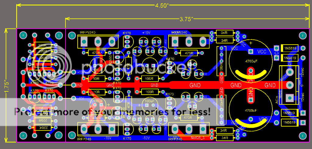
samoloko said:Is It possible to redraw the layout so the backs of the mosfets are outside - that would make complete shunt reg and B1 - so there will be more Interest
There is a reason he put the Mosfets that way. To keep the gate stoppers at minimum distance. That circuit is LED fix V referenced and optimized for that current range. From there you are on your own. It is not meant by me for general scalable regulator use. There is a dedicated regulator thread with discussion and recommended board that can be configured for positive or negative.
xaudiox said:i can try redo the layout in protel.. i'm also thinking if we can have the board with scoring line in between the b1 and the regulator.. so anyone can use the regulator by itself.
Protel: very professional! Scoring: good idea Maybe panelize two pcb with scoring line. Nearly everybody is asking for 2 pcs at least.
samoloko said:Is It possible to redraw the layout so the backs of the mosfets are outside - that would make complete shunt reg and B1 - so there will be more Interest
Yes, nice, but in this way you have symmetrical tracks
Ryssen said:
Sounds fine,can you make 2 more mounting holes for the PSU?
Mandatory!
More ideas:
> Reduce a bit the size of the 2 caps in // to the led strings and keep 'emt close to the leds. It's only a 100 uF/16V elcap!
> Don't use too many hole diameters: 0.8 mm for resistors, leds, caps and TO92 devices, 1 mm for Mosfets, AC connector, diodes and mounting holes. Too many different diameters make the pcb more expensive, while it's quite easy to enlarge holes in a single sided pcb (without metallized holes)
We will end up with nearly 200 pcbs.....Ryssen said:123 boards..")

Hello,
Thanks for the initiative.
I am interested in 6 to 10 boards.
As mentioned in post 102 there is good reason to put the mosfets where they are. Now that some rework on the layout is considered I would nevertheless encourage to foster the option of rearranging the mosfets in such a way that they can be mounted to a larger heatsink. This way it would take only one effort to achieve versatility, and with with a scoring line in between b1 and the regulator no other pcb-version has to be designed. One suggestion is to have the option to mount the mosfets from the underside of the board and bend them aside. This way the pcb might be mounted flat on/parallel to a heatsink. When I see it right on one side this already is possible, so the re-layout would only focus the other half of the pcb. Just a suggestion.
Arjen.
A very good suggestion!av-trouvaille said:Just a suggestion.
- Home
- Group Buys
- GB for DC coupled B1 buffer with shunt PSUs