First, I am for doing the "full meal deal".  Buffer, Shunt PS, Relay PS and Source Relays on one board.
Regarding the dual bridge supply, I am unable to find the posts that explain why this won't work. I did find comments regarding the grounding scheme of the dual bridge supply, but that should be easy to fix unless I'm missing something. Either way, it's not a deal killer to me. I can live with the single bridge, but I prefer the double.
I also second the TO-220 diode footprint option, as I really like the MUR8xx diodes.
I really appreciate everyone's design input and Xaudiox's excellent PCB skills. I believe that the latest board is close to perfection and a very elegant solution. Load that baby with your favorite parts, add a transformer, volume control, source switch and behold..... instant buffer/preamp.
Just my opinion, so take it for what it's worth. (Which isn't much. )
Buffer, Shunt PS, Relay PS and Source Relays on one board.Regarding the dual bridge supply, I am unable to find the posts that explain why this won't work. I did find comments regarding the grounding scheme of the dual bridge supply, but that should be easy to fix unless I'm missing something. Either way, it's not a deal killer to me. I can live with the single bridge, but I prefer the double.
I also second the TO-220 diode footprint option, as I really like the MUR8xx diodes.
I really appreciate everyone's design input and Xaudiox's excellent PCB skills. I believe that the latest board is close to perfection and a very elegant solution. Load that baby with your favorite parts, add a transformer, volume control, source switch and behold..... instant buffer/preamp.
Just my opinion, so take it for what it's worth. (Which isn't much.
)My 2C:
> Return to basic: the first idea of a simple single sided board as originally designed by Crt (with mosfet not to be heatsinked), for those who would like to build just the simmetric B1 w/shunts. This pcb can be done in a while, approved and manufactured w/o proto: it works and doesen't buzz. I personally suupport this idea.
> Design a new board, single voltage, good for V+ and V- (actually two pcbs with scoring) for the shunt itself. For those who mainly want to build a good multi purpose p.s.
> Think about a "fully integrated buffer design" with as many features as people like, including, maybe, a lightspeed attenuator. It will take time, at least a proto, etc., It could become a sort of kit, if we develop the pcb around a nice case and we can eventually have some boxes predrilled and silkscreened by a manufacturer. I'm thinking about the Italian hifi2000 and its Galaxy Series (with 10mm aluminum sides, those cases can provide an adeguate heatsinking). I think they can make it for > 25-30 units
Those that want only a shunt power supply can not really comment as this thread is about a buffer with shunt power supply. Let alone the lightspeed. Let us not make things more complicated than they already are.
If a separate power supply board is offered that is OK but let us not forget the goal of a buffer with power supply. No questions if the power supply can deliver xxx mA into a device xxx please. There is a separate thread about Salas shunt regs with PCB designs.
The more question marks are raised and the more options people want to see the less chance it will be finished.
Just wait for what xaudiox designs.
jean-paul said:Those that want only a shunt power supply can not really comment as this thread is about a buffer with shunt power supply....
... If a separate power supply board is offered that is OK but let us not forget the goal of a buffer with power supply. No questions if the power supply can deliver xxx mA into a device xxx please. There is a separate thread about Salas shunt regs with PCB designs....
You're absolutely right, but many people asked for a pcb with scoring line (to get rid of the buffer, I presume), 4 mounting holes in the P.S. section, mosfets with different orientation for heatsinking (to increase current/voltage as not really needed for this project), etc., etc.
That's whay I thought: if they want just a p.s. pcb, they can open a new GB thread for those.
As far this project is concerned, let's return to the original pcb design by Crt: cheap, tested and ready.
Then (and later) we can think about an improved fully featured pcb for thiose who really want it.
I can't see why we can't satisfy nearly all people here:
1. Do full blown board, but with score lines between PS and buffer, and then another between buffer and relays.
2. Second, simple PS on the PS board suitable for any use (including muting relay)
3. Cost might be more for full option, but either you are in or out. $5 more ain't that much and if there are extra features you don't need, just ignore them.
4. If you want very simple version, maybe if the earlier files were mae available, people could etch their own. If its single sided this is easy to do.
At the end of the day, we are going to get whatever xaudiox gives us Lets be grateful and take it!! If we get bogged down in endless discussions then it will be like the NS10/PS thread where all we get are slightly different versions and no actual PCBs.
I'll take whatever I'm given, the simple solution or the full blown!
Fran
1. Do full blown board, but with score lines between PS and buffer, and then another between buffer and relays.
2. Second, simple PS on the PS board suitable for any use (including muting relay)
3. Cost might be more for full option, but either you are in or out. $5 more ain't that much and if there are extra features you don't need, just ignore them.
4. If you want very simple version, maybe if the earlier files were mae available, people could etch their own. If its single sided this is easy to do.
At the end of the day, we are going to get whatever xaudiox gives us
Lets be grateful and take it!! If we get bogged down in endless discussions then it will be like the NS10/PS thread where all we get are slightly different versions and no actual PCBs. I'll take whatever I'm given, the simple solution or the full blown!
Fran
Let's just see what we can get done and how quickly we can do it, using the original crt design. Then we can be done with that part and everyone can get their boards quickly.
There is /was a GB for a preamp and power supply that is still stalled after many month now and I don't want to see that happen here.
We have a proven tested design for a B1-shunted power supply board, lets make them and ship them. I would be happy to assist in any way I can and would consider doing the work of having them shipped to me to save shipping for the buyers in the states.
That being said I also love the ideas being put forth regarding relays and power supply, scored board and would like to participate in that as well and am willing to invest some time and money into doing some proto work should we take it further.
WIKI
Gent's,
I created a Wiki for sign up. It's basic now. Feel free to edit parameters as it makes sense. Once it get's big enough I will back it up in case someone blows it up by accident.
http://www.diyaudio.com/wiki/index.php?page=GroupBuyDirectCoupledBOne
Gent's,
I created a Wiki for sign up. It's basic now. Feel free to edit parameters as it makes sense. Once it get's big enough I will back it up in case someone blows it up by accident.
http://www.diyaudio.com/wiki/index.php?page=GroupBuyDirectCoupledBOne
Re: WIKI
WOW.. Thanks very much.. i've been trying for hours now but with no luck... thanks again..
Tea-Bag said:Gent's,
I created a Wiki for sign up. It's basic now. Feel free to edit parameters as it makes sense. Once it get's big enough I will back it up in case someone blows it up by accident.
http://www.diyaudio.com/wiki/index.php?page=GroupBuyDirectCoupledBOne
WOW.. Thanks very much.. i've been trying for hours now but with no luck... thanks again..
sorry for the late reply guys.. been sleeping all day ( graveyard shift work) .
i havent read all the replies but this is what i've done so far.. very sorry again for the super size photos.. if its too big just let me know so that i could resize them.
we have 2 versions currently.. basic and deluxe B1.. hehe
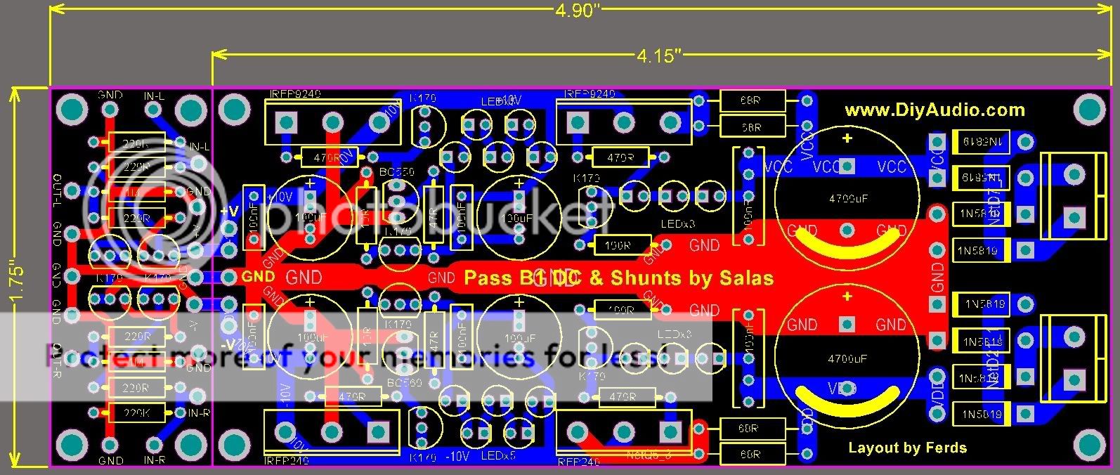
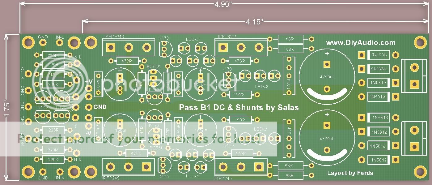
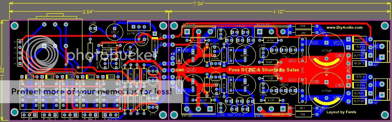
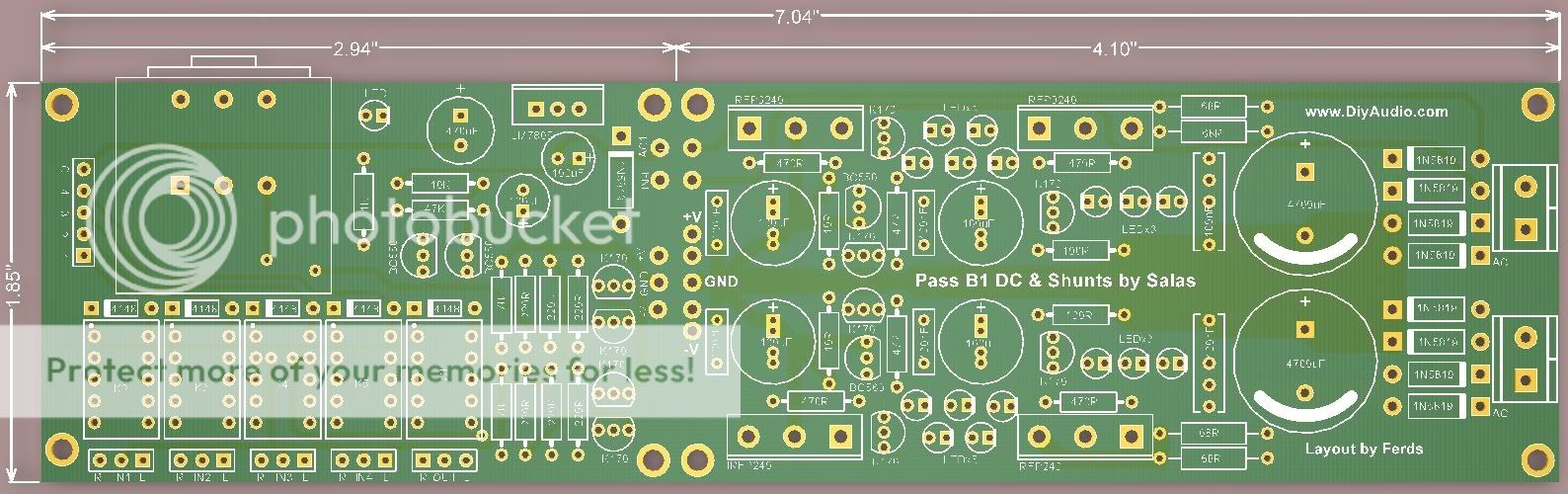
i've change the relays from RY5W-K to TQ2 types.. please check the footprint and pin config of the relay..
i also added alps pot in the pcb as suggested by jean-paul.
this is just a quick layout that i've done today.. did'nt had the time yesterday due to some work..
thanks
i'll reply more later...
.i havent read all the replies but this is what i've done so far.. very sorry again for the super size photos.. if its too big just let me know so that i could resize them.
we have 2 versions currently.. basic and deluxe B1.. hehe
i've change the relays from RY5W-K to TQ2 types.. please check the footprint and pin config of the relay..
i also added alps pot in the pcb as suggested by jean-paul.
this is just a quick layout that i've done today.. did'nt had the time yesterday due to some work..
thanks
i'll reply more later...
ccliu said:I also update the GB wiki, split the "quantity" field to "Basic B1" and "Deluxe B1" to calculate the requirement of these two version. Is it OK?
I am sure it is.
My only reservation is that the "Basic" is a tested design and the "Deluxe" has not been prototyped yet.
Edit: Forgot to say, The boards look great, excellent work, thanks Ferds.
Makes sense - thanks - I have updated my entry.ccliu said:I also update the GB wiki, split the "quantity" field to "Basic B1" and "Deluxe B1" to calculate the requirement of these two version. Is it OK?
Yes,but as there are only a pdf file on that,it has to be redone,andt it is in post 141.But I think that has to be tested to.Well lets wait and see whatAs far this project is concerned, let's return to the original pcb design by Crt: cheap, tested and ready.
xaudiox says.
billyk said:My only reservation is that the "Basic" is a tested design and the "Deluxe" has not been prototyped yet.
We should make clear what exactly is meant with "basic":
Is it Ferds' design without relais or is it crt's original single sided layout?
Personally, after having tasted Ferds' beautiful layout I would not like
to go back to the single sided one...
billyk said:
I am sure it is.
My only reservation is that the "Basic" is a tested design and the "Deluxe" has not been prototyped yet.
True, i'll build prototype boards for both version and will test them together.. i already have most of the parts except for the relays. i can probably do it early next week.. thanks
- Home
- Group Buys
- GB for DC coupled B1 buffer with shunt PSUs