Indeed, you reminded me my first time LDR encounter.udailey said:only 1mA is more than enough to run these guys properly!! Amazing isnt it?
Uriah
I hooked up one DMM at mV range across the 100R and one DMM across the LDR pins. While I was turning the pot, the resistance kept dropping (from 200K to 20K) as expected, but the mV remained at ZERO. I thought I did something wrong and powered off everything in record time, LOL.
PCB terminal blocks
If anyone is worried about soldering heat damage PCB terminal blocks work quite well http://www.futurlec.com/ConnTerm.shtml . This way you can solder everything to the terminal block and not the optocouplers.
Garrett
pchw said:
BTW, if you have slow hands like me, use a alligator clip in the between the soldering point and the LDR "body", it will help reducing the heat damaging the LED. You will be surprised that even a small paper clip can also be used !!
If anyone is worried about soldering heat damage PCB terminal blocks work quite well http://www.futurlec.com/ConnTerm.shtml . This way you can solder everything to the terminal block and not the optocouplers.
Garrett
Hi Uriah, i have done this design starting from your caveman one ")
LSA works nice and has a confortable log range but i have a strange situation:
Overall impedance is about 200k at start and it goes down to 70k at -10/12dB position, than up to 200k again to the end at 0dB.
At -6dB my amp shows a lot of noise (too high output impedance, i think).
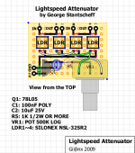
Wonderful selection of LDRs so i decided not to use a balance control and to make a very simple design instead (attached).
I have an optimal listening position and symmetrical fornitures, etc.
Is there something wrong in my design? Maybe that 1k resistor in series with some part or the entire 500k pot (floating impedance)? Maybe 500k is too high when using additional 1k (high total impedance)?
I don't know, i controlled everything 4/5 times but i can't understand.
LDR fried? I don't think so, by the way the attenuator works.
Vout= 4,96V from 78L05, no shorts, ldrs soldered carefully and awaiting a bit for each pin, especially for led sides.
Uriah, Andrew...help me!!!
LSA works nice and has a confortable log range but i have a strange situation:
Overall impedance is about 200k at start and it goes down to 70k at -10/12dB position, than up to 200k again to the end at 0dB.
At -6dB my amp shows a lot of noise (too high output impedance, i think).
Wonderful selection of LDRs so i decided not to use a balance control and to make a very simple design instead (attached).
I have an optimal listening position and symmetrical fornitures, etc.
Is there something wrong in my design? Maybe that 1k resistor in series with some part or the entire 500k pot (floating impedance)? Maybe 500k is too high when using additional 1k (high total impedance)?
I don't know, i controlled everything 4/5 times but i can't understand.
LDR fried? I don't think so, by the way the attenuator works.
Vout= 4,96V from 78L05, no shorts, ldrs soldered carefully and awaiting a bit for each pin, especially for led sides.
Uriah, Andrew...help me!!!
Attachments
Gianni,
Nothing wrong with your schematic as all. Looks fine to me.
At 400k I took the last reading on your LDRs and the pot is 500k which I recommended because 400k is probably not possible to source. For example if your LDRs were 15k at 400k I would expect somewhere around 25k with 500k. NOT 200k. Thats really wild. Is it possible for you to try a pot with a value of 200k-400k? If you have something like that available to you I would try that out.
Do BOTH channels exhibit this weird 200k, 70k, 200k ?
Was this measured from input to ground on signal?
I would measure each LDR in the circuit and also from signal in to signal ground. You MIGHT have a fried LDR, but I dont know yet.
Try these experiments and let me know what you get.
Uriah
Hi Uriah, thanks for the quick reply.
I will do some tests with a 250k these days, i don't have so much time in working days.
Yes, both channels have same weid "sinusoidal" overall impedance, from signal to ground.
They are well matched if i measure one by one, shunt ones a bit less, but it's ok.
The result, noise included, is that all the sound is "soft and too warm", due to the impedance i think.
LDRs still give me a measure, all together and one by one.
200k is nothing...with the pot completely turned down or up, i read over 4Mohm!!!
I think that 1k or the value of the pot or both are too much...
Regards,
Gianni
with a single track 500k pot and the 5V fed to the wiper:
The LEDS see 1k0 + 500k/2 when in the middle position.
At full volume or at minimum volume the LEDs see 1k0 + 500k or 1k0+~0k1
The currents passing in these conditions are minimum 3V/501k=6uA, medium 3V/251k=12uA, maximum 3V/1k1=~2800uA
I cannot see how the LDRs can go from 200k to 70k to 200k for those LED currents. There must be a wiring fault or you have confused us with your explanation of what you have measured.
Can we also have close up pictures of your wiring? I wonder if you are using the pot that I sent or another 500k pot. If your pot has an on/off feature this is the only way I can imagine a 4MOhm resistance.................
Ohhhhhhh. You know what, your LM7805 is having a hard time keeping stable and the voltage is diving because it does not see a load at all and thats why you are getting 4MOhm. It is also why you are getting 200k, because the voltage is diving which also changes the resistance of the LDRs.
Put a resistor from output to ground on your LM7805. Pick something from 100-500Ohms or so. Give it appropriate sizing so it doesnt fry. You need a load on your regulator.
Andrew do you agree?
Uriah
Thanks Andrew,
200k to 70k to 200k is referred to a measure from the input to signal ground.
200k at nine, 70k at twelve and 200k again at three.
Over 40Mohm at full down or up, maybe they go off, in fact the volume goes to complete silence and when i turn clockwise a bit i heard a little click.
LSA works and correctly attenuates. Wiring is strictly the same in the picture posted before. I'm not an engineer but not really a newbie. No polemics, it's just to help you.
I thought that a mismatch among LDRs (series and shunt) could make the entire resistance float. Maybe soldering and heating too much but...exactly in both channel???
When i completely turn down the pot i read 1,65V between the pot pin and ground, the same on the other side with the pot at full. I will control EVERYTHING again and let you know the news. I will post photos of the "THING", I hope i will be more precise, despite my english!
Thanks for your precious time.
Regards,
Gianni
Last edited:
Uriah, i only use pots with on/off when i build small guitar amps!
It's the pot that you sent, measuring 496k, so it's ok.
For the regulator, read also my previous post, where i talk about 1,65V at extreme opposite positions. You mean that the current drawn by the LDRs is not sufficient for it?
Uhm, it can be a possibility, too much small load? I'll give it a try, but... it's your design, there's no other one that tried with a 7805 on top? I don't think so...
Oh my god, it should be the easiest thing that i did!
Ciao, (you know "ciao", don't you?)
Gianni
I think most people are using whatever they want for a power supply. I use LM317LZ twice with parallel resistor. You are the only person to experience this particular problem. There have been two other problems that were quickly sorted. Yours will work when the regulator is working.
Uriah
Have spent time in Italy so I am familiar with Ciao also very familiar with Grappa!
Uriah
Have spent time in Italy so I am familiar with Ciao
also very familiar with Grappa!When the pot is at min of the max, the 5V will be in series with the 1K and (the shunt's or the series) LDR's. That will be the load, and one of the LDR (per channel) is at "full throttle", and one is at full attenuation. The reading of 4 meg ohm in this position isn't abnormal because one of the LDR's is fully shut. 200K at 9 o'clock seems to be a little high, typically, you will enter the 10K-25K range from 9 o'clock to 3 o'clock and remains relatively constant.
A couple things:
- how did you measure to get 1.65V? From L/R pin of pot to ground?
- can you measure the voltage across the 1K resistor when pot is min, 9, 12, 3 positions?
- try this, disconnect one channel of LDR's and report back the same measurements that you did.
A couple things:
- how did you measure to get 1.65V? From L/R pin of pot to ground?
- can you measure the voltage across the 1K resistor when pot is min, 9, 12, 3 positions?
- try this, disconnect one channel of LDR's and report back the same measurements that you did.
- Status
- This old topic is closed. If you want to reopen this topic, contact a moderator using the "Report Post" button.
- Home
- Group Buys
- Silonex LDRs for Lightspeed Attenuator