
Hi Vernon,
One bag is for shunt and one for series. A few posts back I described how to determine which to use, but frankly the balanced bags are so well matched that I dont think it will make a difference. Go back and read about how to figure out which is which and if you still have questions shoot me an email and we will sort it out. In your email tell me one LDR number from each bag.
Uriah
Okay,
So go to this page and print it out
http://picasaweb.google.com/udailey/LDR#5332725957653943554
Now notice how a dual gang pot is tied together with wires. If you know how a potentiometer works this will be easier to understand. If not go here and read up til you understand how it works and which is the wiper and how it works.
http://sound.westhost.com/pots.htm
So the dual gang pot is tied up with a bunch of connecting wires. Important right now is just how they connect the legs together. Notice how 3 and 1 are tied together. Notice how on each side of 3 and 1 the other legs are tied together. Think about what has happened here. Lets call the connection of 1 and 2 twelve (12). Notice how now we have a variable resistor between 3 and 12. We also have a variable resistor between 1 and 23 of the second gang. we have made two rheostats.
http://sound.westhost.com/pots-f6.gif Look at this picture. We have made two of the third example in the pic out of the fourth example. Look at this part until you understand it. We have to be clear on this point.
If you can see how we have two variable resistors thats great and we can proceed.
Now, consider what is the value of those two variable resistors? If the first resistor is X Ohms and the second resistor is Y Ohms and the original resistance of the pot is Z then ALWAYS
Z=X+Y
X=Z-Y
Y=Z-X
So at 0 volume X =100k and Y=0
At full volume X=0 and Y=100k
At 1/4 volume X=25k and Y=75k
See the relationship?
Consider a single gang pot with three tabs like the first example in the picture I last gave a link for. We just created this with the dual gang pot by tying 1 and 3 of the two gangs together and then tying 1 to 2 and 2 to 3 of the first and second gang respectively.
Can you see how if the circuit works with a dual gang pot tied up to be a single gang pot that a single gang pot ought to work?
Now... Why would the volume increase evenly on both speakers?
We have series resistors and we have shunt resistors. By 'resistors' I mean LDRs. Series resistors restrict the current and therefore the amp has to amplify a very tiny signal when the LDR has max resistance. Since we call it the series resistor we can assume it is in "series" with the source and amplifier.
The first gang of that pot that is now a variable resistor controls the series LDRs. The single variable resistor controls BOTH of the series LDRs so when the resistor is fully dark, max resistance, then the signal is as small as it will get and the speakers are both silent. Turn the pot a bit to the right and the value of this resistor gets smaller, more current comes through, and the speakers get louder.
The OTHER gang creates the variable resistor that controls the shunt LDRs. Each side.. L and R.. have a shunt resistor or LDR that goes from the output of the series resistor to ground. When we turn the pot to the right and the series LDRs increase in resistance the second gang of the dual pot decreases in resistance, letting through more current, lighting up the LED in the shunt LDRs equally, and therefore the shunt LDRs have less resistance.
What the heck are the shunt LDRs for anyway? Well again lets look at the first example of the last pic I linked. Notice how the number 2 pin on that potentiometer in the pic goes to the amp. Pin 3 goes to ground. The resistance between pins 1 and 2 are performing the same function as the shunt LDR. If the series resistor simply increased and decreased in resistance then we would have volume increase and decrease but we would be missing something. We would be missing a stable output impedance from our preamp. Thankfully the Shunt LDR moves in exactly the opposite direction of the series LDR all the time. This allows X+Y to equal Z. Z is the output impedance. If we did not have this relationship then the output impedance would fluctuate all the time and would sound bad if not harm your source or amp.
")
URIAH
So go to this page and print it out
http://picasaweb.google.com/udailey/LDR#5332725957653943554
Now notice how a dual gang pot is tied together with wires. If you know how a potentiometer works this will be easier to understand. If not go here and read up til you understand how it works and which is the wiper and how it works.
http://sound.westhost.com/pots.htm
So the dual gang pot is tied up with a bunch of connecting wires. Important right now is just how they connect the legs together. Notice how 3 and 1 are tied together. Notice how on each side of 3 and 1 the other legs are tied together. Think about what has happened here. Lets call the connection of 1 and 2 twelve (12). Notice how now we have a variable resistor between 3 and 12. We also have a variable resistor between 1 and 23 of the second gang. we have made two rheostats.
http://sound.westhost.com/pots-f6.gif Look at this picture. We have made two of the third example in the pic out of the fourth example. Look at this part until you understand it. We have to be clear on this point.
If you can see how we have two variable resistors thats great and we can proceed.
Now, consider what is the value of those two variable resistors? If the first resistor is X Ohms and the second resistor is Y Ohms and the original resistance of the pot is Z then ALWAYS
Z=X+Y
X=Z-Y
Y=Z-X
So at 0 volume X =100k and Y=0
At full volume X=0 and Y=100k
At 1/4 volume X=25k and Y=75k
See the relationship?
Consider a single gang pot with three tabs like the first example in the picture I last gave a link for. We just created this with the dual gang pot by tying 1 and 3 of the two gangs together and then tying 1 to 2 and 2 to 3 of the first and second gang respectively.
Can you see how if the circuit works with a dual gang pot tied up to be a single gang pot that a single gang pot ought to work?
Now... Why would the volume increase evenly on both speakers?
We have series resistors and we have shunt resistors. By 'resistors' I mean LDRs. Series resistors restrict the current and therefore the amp has to amplify a very tiny signal when the LDR has max resistance. Since we call it the series resistor we can assume it is in "series" with the source and amplifier.
The first gang of that pot that is now a variable resistor controls the series LDRs. The single variable resistor controls BOTH of the series LDRs so when the resistor is fully dark, max resistance, then the signal is as small as it will get and the speakers are both silent. Turn the pot a bit to the right and the value of this resistor gets smaller, more current comes through, and the speakers get louder.
The OTHER gang creates the variable resistor that controls the shunt LDRs. Each side.. L and R.. have a shunt resistor or LDR that goes from the output of the series resistor to ground. When we turn the pot to the right and the series LDRs increase in resistance the second gang of the dual pot decreases in resistance, letting through more current, lighting up the LED in the shunt LDRs equally, and therefore the shunt LDRs have less resistance.
What the heck are the shunt LDRs for anyway? Well again lets look at the first example of the last pic I linked. Notice how the number 2 pin on that potentiometer in the pic goes to the amp. Pin 3 goes to ground. The resistance between pins 1 and 2 are performing the same function as the shunt LDR. If the series resistor simply increased and decreased in resistance then we would have volume increase and decrease but we would be missing something. We would be missing a stable output impedance from our preamp. Thankfully the Shunt LDR moves in exactly the opposite direction of the series LDR all the time. This allows X+Y to equal Z. Z is the output impedance. If we did not have this relationship then the output impedance would fluctuate all the time and would sound bad if not harm your source or amp.
URIAH
I also have to admit that I need to mess with pots a little more and try some experimentation. Pots are defined as being a voltage divider. To me it makes sense that they restrict current. For sure in the LDR circuit the pot that runs the LDRs restricts current because really it is not a pot but two variable resistors that look a bit like a pot after our modifications. But I am not sure whats up with a regular pots being a voltage divider and since a series resistor will restrict current, why doesnt anyone mention current drops in a pot? I dont know but I should get out the DMM and mess around to see whats going on.
Uriah
Uriah
Is this how you suggest to connect the mono pot ?
btw, those pots are made for guitar use, and reason why there are no double log pots
But I have seen some stacked ones
Probably not very precise, but that obviously doesnt matter so much
btw, those pots are made for guitar use, and reason why there are no double log pots
But I have seen some stacked ones
Probably not very precise, but that obviously doesnt matter so much
Attachments
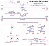
Hi T,
no,
You have the signal lines OK.
one series LDR in each line and one shunt LDR for each line.
To get these to work as an attenuator you require that the resistance of the shunt LDR moves in the opposite direction to the resistance of the series LDR.
eg.
shunt LDR=1k0 Series LDR=50k Rin of load 50k, Rs=200r.
The 1k0 & the 50k load are // effective R=980r4
The series resistance is 50k + 200r = 50k2
Attenuation = 980.2/{980.2 + 50k2} = 0.0195 = -34.4dB
Now adjust the LED supply current to reduce the Series resistor and increase the shunt resistor. Say the adjusted values are
Rseries=10k Rshunt=12k
attenuation is based on 50k//12k and 10k+200r
giving 9k677 for effective shunt and 10k2 for effective series.
Attenuation = 9k677/{9k677+10k2) = 0.487 = -6.3dB.
For attenuation to work correctly the series and shunt LEDS must adjust in opposite directions.
Right
Seems Im a bit too lazy, and should have measured on pot
Then its quite obvious
 to my excuse, I have only mounted a pot once in my life, many years ago
But wonder why George use a stereo pot, but probably just a matter of convenience and durability, I guess
btw, many of these small high impedance pots seems to be made especially for el-bass/guitars
Another point
Why not use a pot for channel balance, instead of multiturns
Will it be too sensitive, and hard to adjust
Seems Im a bit too lazy, and should have measured on pot
Then its quite obvious
to my excuse, I have only mounted a pot once in my life, many years agoBut wonder why George use a stereo pot, but probably just a matter of convenience and durability, I guess
btw, many of these small high impedance pots seems to be made especially for el-bass/guitars
Another point
Why not use a pot for channel balance, instead of multiturns
Will it be too sensitive, and hard to adjust
Attachments
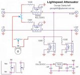
Some suggestions:
If you are concerned about the durability of the pot then put the protection resistor in front of the pot rather than behind it before the LDRs. Just stick any 100Ohm resistor on the wiper and then give the resistor the 5VDC.
Now the pot will only see 50mA. Pretty easy to implement.
Before this change the 100Ohm resistors are in front of the LDRs and after the pot. They are in series between the pot and LDRs but in parallel to each other so we have 100/4=25Ohms giving us 200mA or 1W if it were possible for each variable resistor to be at 0Ohms at the same time. Since thats not then the extreme would be about half of that or 1/2Watt. I have a 1/2 watt dual gang pot running on mine and have no issues, but I also have a near endless supply of LDRs so I am not so concerned about losing an LDR or 4. You might try that mod.
YES! I fully agree that a pot instead of a trimmer is nicer to use for balance control. Thats what I use. I had a 10 turn 5k pot in a drawer and thats what it gets used for. I like the multiturn but on the other hand it would be nice to notice the difference in balance changing quickly with a single turn pot. Its a little fiddly with a multiturn.
George has used both dual and single gang pots. If you think about it the way I described it there is really no difference between the single gangs and modifying the dual gang EXCEPT the power load that the pot can handle. The pots I sent out are half watt pots. AndrewT had expressed concern that they wouldnt work well because of their low wattage but I tend to disagree with him. As a caveat, the guy is hardly ever wrong and I am often wrong, but it makes sense to me that this pot is fine since we are using it as a dual variable resistor rather than a pot that is referenced to ground. These dual resistors we created tame down the current rather than acting as a small load and with the 100ohm resistors in place your LDRs are safe if anything nasty happens but feel free to bump them up to 100-1k if it bothers you. Or if thats what you have in the parts bin. Especially with these LDRs 1k wont make much difference in the resistance of the LDR but will take the amount of current down to near nothing.
Uriah
If you are concerned about the durability of the pot then put the protection resistor in front of the pot rather than behind it before the LDRs. Just stick any 100Ohm resistor on the wiper and then give the resistor the 5VDC.
Now the pot will only see 50mA.
Pretty easy to implement.Before this change the 100Ohm resistors are in front of the LDRs and after the pot. They are in series between the pot and LDRs but in parallel to each other so we have 100/4=25Ohms giving us 200mA or 1W if it were possible for each variable resistor to be at 0Ohms at the same time. Since thats not then the extreme would be about half of that or 1/2Watt. I have a 1/2 watt dual gang pot running on mine and have no issues, but I also have a near endless supply of LDRs so I am not so concerned about losing an LDR or 4. You might try that mod.
YES! I fully agree that a pot instead of a trimmer is nicer to use for balance control. Thats what I use. I had a 10 turn 5k pot in a drawer and thats what it gets used for. I like the multiturn but on the other hand it would be nice to notice the difference in balance changing quickly with a single turn pot. Its a little fiddly with a multiturn.
George has used both dual and single gang pots. If you think about it the way I described it there is really no difference between the single gangs and modifying the dual gang EXCEPT the power load that the pot can handle. The pots I sent out are half watt pots. AndrewT had expressed concern that they wouldnt work well because of their low wattage but I tend to disagree with him. As a caveat, the guy is hardly ever wrong and I am often wrong, but it makes sense to me that this pot is fine since we are using it as a dual variable resistor rather than a pot that is referenced to ground. These dual resistors we created tame down the current rather than acting as a small load and with the 100ohm resistors in place your LDRs are safe if anything nasty happens but feel free to bump them up to 100-1k if it bothers you. Or if thats what you have in the parts bin. Especially with these LDRs 1k wont make much difference in the resistance of the LDR but will take the amount of current down to near nothing.
Uriah
I dont know where my head has been. Those 100ohm resistors are NOT in parallel to each other since they terminate into the LEDs. Since only two of them will be getting any significant mA at a time, either series or shunt depending on position of volume control pot, then we just add the max possible amount of mA through the two. 5VDC through a minimum possible 0Ohms on a fully on or fully off volume pot to two 100Ohm resistors. 5VDC through a 100ohm resistor gives us .05A or 50mA. This is an extreme folks and its only if your volume pot if full on/off. So two resistors doing that will pull 100mA through the pot and at 5VDC thats .5W. The max rating for that pot.
If we were to put a 100Ohm resistor in front of the pot rather than following it we get only 50mA or 250mW through the pot.
So I have to say that I have had no problems with the Lightspeed circuit AS IS and I have been running it for over a half a year. That said, next time I build one I will be putting a 680Ohm in front of the pot.
Uriah
I just had a customer tell me he broke the legs off of his LDR. The LED legs. They are not round so they only bend in two directions and should not be bent anyway. Dont bend the LED legs. They are fragile. Dont heat them but heat the component or wire or through hole you will be connecting them to. Then let the solder flow and it will heat the leg. Be careful and be quick. To much heat on the LED leg and the LED characteristics will change. Then it wont match anymore.
Uriah
Uriah
I tested. At full blast, the 100R limits the current drawn by the LDR at approx. 30ma which exceeds the specs. I found upping the 100R to 500R would drop this number to 6ma which is more than enough to lower the LDR output resistance to lesser than 100R (BTW, use a 330R will limit to 9ma). As Uriah said, there can be only 2 are in full blast (one pair at full attenuation, and one pair at wide open). Remember, the series and the shunt are see-saw-ing the current demand. So, the pot will only see 2X of this limit passing through all the time, not 4X.
I also found that 1ma was enough to drop the LDR's output resistance to lesser than 1K. So, feel like more protection? Up the 100R all the way to 1K, then the total current through the pot will never be exceeding the spec, 2 x 3ma = 6ma < the safe limit that AndrewT computed!!! If you have a 5K balance trimpot in series with each LDR, simply crank each one of these up a few hundred ohms. This will have the same effective protection.
BTW, if you have slow hands like me, use a alligator clip in the between the soldering point and the LDR "body", it will help reducing the heat damaging the LED. You will be surprised that even a small paper clip can also be used !!
- Status
- This old topic is closed. If you want to reopen this topic, contact a moderator using the "Report Post" button.
- Home
- Group Buys
- Silonex LDRs for Lightspeed Attenuator