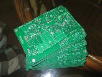
Here is the pdf for the hv reg. My old site is down. So I've put it up here.
http://www.basaudio.net/datasheets/hvreg.pdf
http://www.basaudio.net/datasheets/hvreg.pdf
Heat issue on FET
hello again! ?
planning to run this with 75mA@410-420vdc to 300B b+
have discussed the implementation of this reg. on a Norwegian forum, and there has been suggested that heat dissapation from the FET might be an issue;
would a possible solution be to parallell 2 FETs, to bring the heat down on each?
could no 2 be "mirror fixed" on the underside of the pcb with it own heatsink?
opinions anyone?
best
Leif
Hi I was wondering who have finished their HV Shunt Reg boards and have them working properly without Oscillation.
What op amp did you use? Anybody get this board to work properly (no oscillation) with the OPA656 op amp?
Thanks, Daniel
Dan, did you ever build and get this reg working properly?
I got a few requests lately for this PCB. I'll make a small run of 10, at 25$ each + shipping and 3%PayPal fee. I already have 4 sold. Let me know at bergeron.syl@videotron.qc.ca.
Thanks...
Thanks...
PCB
Hello,
Are the pcbs still available?
Thanks
Four PCB to Gilwintan
two to jormajj
Only 4 PCB left...
Let me know.
Thanks.
Hello,
Are the pcbs still available?
Thanks
Hi.
I was hoping someone could help me trouble shoot this circuit ?
The board passed the 15V only tests fine. When I apply the HV, things go pear shaped.
I followed the test steps.
When I power on, I get no voltage reading across R12 (it's supposed to be 250mV). Furthermore, adjusting R3 does not alter the VReg.
After poking about with my multimeter, I got the following readings at the opamp :
pin 2 = 7V (fine)
pin 3 = 1.2V (wrong !!!)
pin 6 = 0.9V (correct for mostfet shunt)
pin 7 = 10.6V (correct)
Checking other voltages, the voltages immediately after T2 are way low. RAW DC coming in about 300V, but after T2 the voltages are 65V.
What should the initial position of R3 be ? The documentation has no mention of a default value ...
A big but though ... For about 5 seconds after initial power on, everything looks like it's going to behave, with realistic voltages at the outputs, but then they suddenly drop.
If there's any more info you require, let me know.
I'm at my wits end !
- Home
- Group Buys
- HV Shunt Regulator PCB
