Below a serial XO filter low in component count, lowers the acoustic XO point compared post 409 and based on same frd zma files. Woofer is set 3" behind 10F in schematic so as FR shows offset is build into component values. Capacitor will be expensive if exotic types are used else one could use a non polar electrolytic or solder two polar ones back to back. Guess its something ala this planet10 requested earlier on in the thread for passive.
Looks like both knees need a little work to adjust q and you may have some phase cancellation around 100Hz. I got a similarly huge value cap when I took a look at a series option. Maybe someone that knows more about it can chime in.
tuxedocivic and satx,
Regarding i use frd file measured from actual setup in xrk971 lab room can we say room mode is build into XO filter 🙄. That one satx and tuxedocivic is welcome answer, and not because using reference measurement from anechoic enviroment is wrong at all, but can i feel there could be some more precision if XO is tuned to room and then speaker ofcourse stay there in that position 🙂. Had looked in some Jeff Bagby spreadsheets and seen room mode how scary it is sometimes just raise height for a driver 10cm to its FR, that's not so much a problem running full ranger but in multi way in the plan where drivers blend gets different FR in different heights, therefore say above because as diy we have the opportunity to tweak that.
Yes, I would say that. You usually don't want to design with room modes present in your xo region. I guess with active and just for your personal use there's no preblem I suppose as long as you never move the speaker or furniture, or open the curtains etc.
This is why I'm not too concerned with using manufacture data adjusted for baffle effects and with phase extacted for my model. I think it's probably better than what you guys are using. Normally I would always says that actual measurement mounted on your baffle are the best, but only if measured correctly. As it is now, I don't think they're measured right, No offence intended, but like tuxedocivic said earlier, do it right or do it again.
Btw, If I was making this speaker, I might make a floorstander of it, with the woofer closer to the floor to minimize floor cancellation and give a little boost on the low end. you already need stands I assume so it would take up the same amount of space and with with the low xo you may not have any lobbing (1st order xo being the possible problem)
PCD simulation of active XO
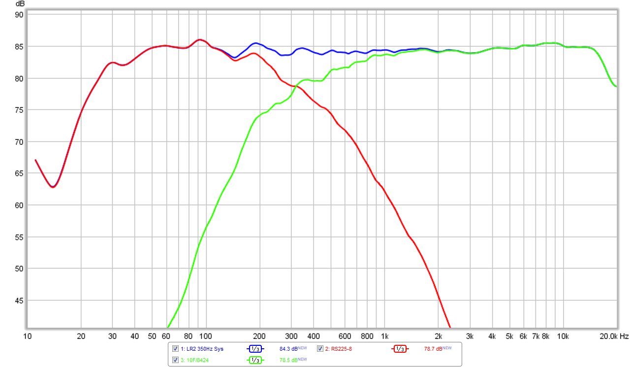
I tested out the PCD to model the active XO for an acoustic 350Hz XO for a LR2 filter and it works well. It helped me to narrow down the settings in miniDSP to get the correct acoustic XO frequency of about 350Hz. The settings ended up being a LPF at 230Hz on the RS225 and HPF at 270Hz on the 10F/8424 to arrive approximately at 350Hz.
Here is the PCD sim:
Here is the measured response (with some mild EQ shaping) the response is now +/- 1.5 dB from 40Hz to 15kHz (for 1/3 oct smoothing):
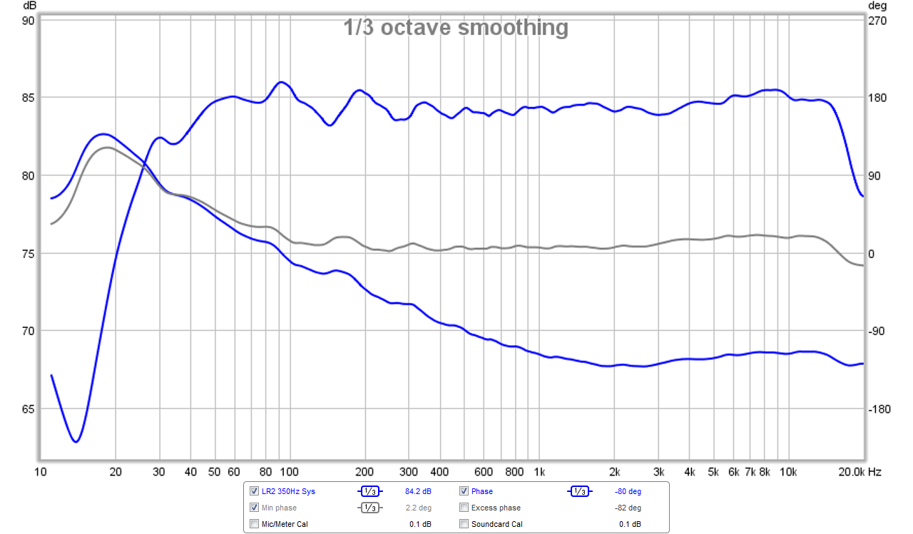
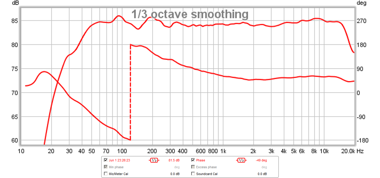
Here is the measured phase (smooth linear variation):
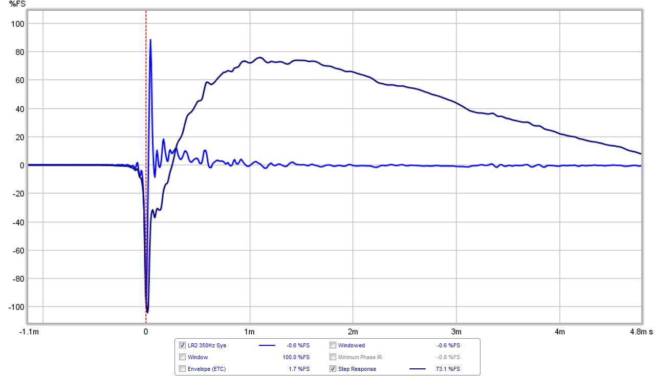
Here is the measured impulse and step response (not transient perfect anymore) with the polarity of the 10F reversed for LR2:
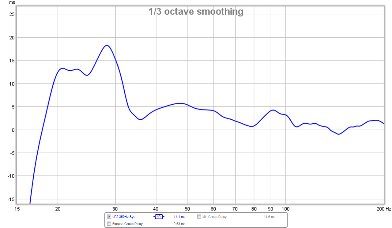
Here is the measured group delay (no infrasonic HPF on RS225) is only +/- 2.5ms down to 33Hz - pretty good:
Did you get a chance to play with the files I sent you X? Figure it out?
I tested out the PCD to model the active XO for an acoustic 350Hz XO for a LR2 filter and it works well. It helped me to narrow down the settings in miniDSP to get the correct acoustic XO frequency of about 350Hz. The settings ended up being a LPF at 230Hz on the RS225 and HPF at 270Hz on the 10F/8424 to arrive approximately at 350Hz.
Here is the PCD sim:
Here is the measured response (with some mild EQ shaping) the response is now +/- 1.5 dB from 40Hz to 15kHz (for 1/3 oct smoothing):
Here is the measured phase (smooth linear variation):
Here is the measured impulse and step response (not transient perfect anymore) with the polarity of the 10F reversed for LR2:
Here is the measured group delay (no infrasonic HPF on RS225) is only +/- 2.5ms down to 33Hz - pretty good:
Attachments


Last edited:
Hey good job! I'm glad you figured it out. Modeling first will definitely make life easier from now on. Can you post a screen shot of the active settings you used?
Did you import your measurements or are you using the ones I gave you still?
I'm confused about how you would get perfect SR even with 1st order filters because don't you need to reverse pol. with that too? Would using asymmetric slopes help you SR?
Did you import your measurements or are you using the ones I gave you still?
I'm confused about how you would get perfect SR even with 1st order filters because don't you need to reverse pol. with that too? Would using asymmetric slopes help you SR?
Also, the model shows the xo at 450, but the actual shows about 325Hz. Do you know what's causing that? Maybe the actual rolloff of the 10f is a little more extended than the sealed box model i did? Or maybe it's just room reflections screwing things up.
Can you post a reverse null measurement?
Can you post a reverse null measurement?
I'm using your FRD curves which is probably why the XO doesn't hit right on the spot. I am still learning so haven't figured out how to import my own curves yet. There are a bunch of little tweaks on the EQ that I applied but still using the 3 PEQ's on the RS225 that you suggested. There is a lot of content in Bagby's PCD for one screen. I would have split them off into separate tabs for easier navigation with a laptop screen. As it is there is a lot of scrolling up and down and left and right. Even on my desktop 1920x1080 monitor it is still too big to see all at once.
I think my big question is the measured phase looking ok now? This is the best I have seen it because the summation is always higher than the individual traces - whereas before it never was perfectly always higher. There was always a region that was below and above.
I think my big question is the measured phase looking ok now? This is the best I have seen it because the summation is always higher than the individual traces - whereas before it never was perfectly always higher. There was always a region that was below and above.
Last edited:
I'm using your FRD curves which is probably why the XO doesn't hit right on the spot. I am still learning so haven't figured out how to import my own curves yet. There are a bunch of little tweaks on the EQ that I applied but still using the 3 PEQ's on the RS225 that you suggested. There is a lot of content in Bagby's PCD for one screen. I would have split them off into separate tabs for easier navigation with a laptop screen. As it is there is a lot of scrolling up and down and left and right. Even on my desktop 1920x1080 monitor it is still too big to see all at once.
I think my big question is the measured phase looking ok now? This is the best I have seen it because the summation is always higher than the individual traces - whereas before it never was perfectly always higher. There was always a region that was below and above.
I agree, there's way too much on one screen, especially when you're designing a three way. If you make changes to the components for the mid you can't see what the response is doing in the graph right next to it, let alone see what, for instance, the transfer function is doing all the way at the top of the screen. This on a 25" monitor.... on the otherhand, it's really a very good and accurate free program so I wouldn't complain too much!
The phase is looking much better, this is why I kept pointing out the problems you were having before and giving you the sims that I did where the problem was fixed. I don't see any cancellation on yours, but if you look at post #378, I gave you an LR2 sim. you'll see that mine has more lift to the sum above the woofer response down low and above the mid up around 2K. This may just be a room artifact in your measurements or maybe the LT is doing something to it on the bottom. Not really a big deal, but that's all I really see.
Can you measure and post a reverse null with sum and individual all overlaid. That would tell more
This is really impressive what can be done with DRC. So would my 10F/RS225 FAST system be a good candidate to get these kinds of results? Can the DRC be applied in stereo before being applied to miniDSP 2x4 which handles the XO and basic EQ? Or do I have to get a dedicated 4ch sound card and let the PC with DRC handle all aspects including XO and FIR filters?
Yes and no.
But that last option gives you even more to play with
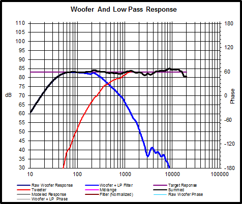
First is stereo correction method. Digital out of sound card feeds DCX2496 which is used solely for 48dB/octave crossover at 1kHz; no EQ and no delay adjustments.
Here is FR for woofer, tweeter, both together, and both together with correction filter:

Square wave is step response test waveform. Swept square wave 5-4000 30sec. is generated and then convolved with IR for raw and corrected conditions. The two responses are aligned in stereo track for viewing:
200Hz square wave:

1600Hz square wave:

Raw square wave response is horrible for both 200Hz and 1600Hz. For 1600Hz square wave response of tweeter isn't very good when run without LR8 1kHz crossover, and is badly mangled by the 360 degree phase rotation with the LR8 crossover.
Raw woofer high pass has approximate 12dB/octave roll off of driver in sealed enclosure. This alone wrecks 200Hz square wave response.
70Hz square wave corrected v raw:

Woofer is 5.25" in 18 liter sealed enclosure!
70Hz square wave for solo uncorrected woofer v simulation with 70Hz Butterworth high pass applied twice to get classic 12dB/octave roll off:

Correlation of simulation v solo woofer puts nail in monkey coffin. No amount of equalization with infinite impulse response type filters, be they active or passive, will clean up the low frequency step response.
Without a reference that is flat in phase and frequency responses, exploration of different IIR XO filters is nearly pointless as demonstrated by countless investigators. IMHO correction of lower octaves to flat FR/phase with DSP inverse correction filters yields greater realism across the broadest range of recordings.
Can you measure and post a reverse null with sum and individual all overlaid. That would tell more
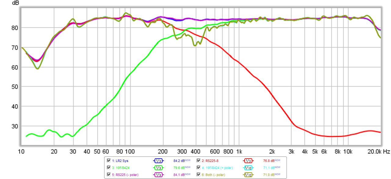
Ok, I tried it with reverse polarity on just the 10F (baseline case from above), then positive polarity on just 10F, then negative polarity on just RS225, then negative polarity on both. I left summed response with 1/2th oct smoothing so you can see depth of cancellation is -12dB. One interesting thing is that with 10F positive polarity and RS225 negative polarity (how Byrtt suggested it be done), the SR is much better and looks at least like a small right triangle rather than a blip.
Here is the XO diagram (all the same sense polarity lines land on top of each other perfectly):
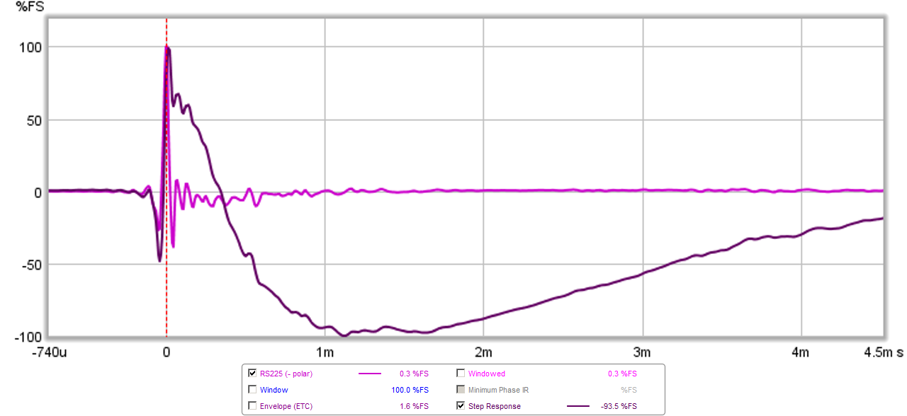
Here is the IR and SR for the case with RS225 negative polarity and 10F positive polarity:
Attachments


Last edited:
First is stereo correction method. Digital out of sound card feeds DCX2496 which is used solely for 48dB/octave crossover at 1kHz; no EQ and no delay adjustments.
Here is FR for woofer, tweeter, both together, and both together with correction filter:
View attachment 485951
Square wave is step response test waveform. Swept square wave 5-4000 30sec. is generated and then convolved with IR for raw and corrected conditions. The two responses are aligned in stereo track for viewing:
200Hz square wave:
View attachment 485952
1600Hz square wave:
View attachment 485953
Raw square wave response is horrible for both 200Hz and 1600Hz. For 1600Hz square wave response of tweeter isn't very good when run without LR8 1kHz crossover, and is badly mangled by the 360 degree phase rotation with the LR8 crossover.
Raw woofer high pass has approximate 12dB/octave roll off of driver in sealed enclosure. This alone wrecks 200Hz square wave response.
70Hz square wave corrected v raw:
View attachment 485954
Woofer is 5.25" in 18 liter sealed enclosure!
70Hz square wave for solo uncorrected woofer v simulation with 70Hz Butterworth high pass applied twice to get classic 12dB/octave roll off:
View attachment 485955
Correlation of simulation v solo woofer puts nail in monkey coffin. No amount of equalization with infinite impulse response type filters, be they active or passive, will clean up the low frequency step response.
Without a reference that is flat in phase and frequency responses, exploration of different IIR XO filters is nearly pointless as demonstrated by countless investigators. IMHO correction of lower octaves to flat FR/phase with DSP inverse correction filters yields greater realism across the broadest range of recordings.
I think what you are trying to tell me is that if an IIR XO is placed in signal path - no amount of DRC upstream will fix phase rotation that makes square waves impossible to achieve. What about BW1 XO downstream of DRC correction?
Ok, I tried it with reverse polarity on just the 10F (baseline case from above), then positive polarity on just 10F, then negative polarity on just RS225, then negative polarity on both. I left summed response with 1/2th oct smoothing so you can see depth of cancellation is -12dB. One interesting thing is that with 10F positive polarity and RS225 negative polarity (how Byrtt suggested it be done), the SR is much better and looks at least like a small right triangle rather than a blip.
Here is the XO diagram (all the same sense polarity lines land on top of each other perfectly):
Here is the IR and SR for the case with RS225 negative polarity and 10F positive polarity:
Thanks for posting that. The reverse null doesn't look great (see post #378, the gray line is with reversed polarity), but it's really hard to tell at those frequencies. If you move the mic even just a little it'll probably look better or worse. Also, I believe I had PCD listening/measuring distance set to 3 meters in the file I sent you, so you might try setting it to your measuring distance to see if it correlates with what you're seeing
Anyways, so how does it sound?
It's the high pass filtering stemming from output stage of preamplifier combination with power amplifier, plus output stage of amplifier combination with speaker's inherent high pass behavior.
This is a perfect example, and coincides with my own experiences. My example is equalizing system flat down to <10Hz and then using brick-wall 20Hz FIR high pass filter. Something wasn't right, so I went to 30Hz 12dB/octave FIR and feel of the air in the room felt (literally) closer to live. Then I skipped the high pass filter and sensed further improvement in sense of venue reverb; this especially with classical music, timpani, acoustic bass. A setting reserved for familiar recordings for sure.
Another look at group delay; analog stages. Using E-MU 0404 USB sound card, DCX2496, and REW the IR was measured for analog sound card loop back, sound card digital out to DCX with DCX output to E-MU line in loop back, and sound card analog output to DCX with DCX output to E-MU line in loop back.
Here are overlays of GD for the three conditions:

Note how GD marked at 70Hz for analog connection of DCX is approximately sum of sound card loop back GD with digital connection of DCX loop back GD.
Here is 70Hz square wave response of E-MU loop back connection (157microsecond GD or 4 degrees relative phase) compared to 70Hz square wave of corrected speaker response:

Sound card GD is responsible for 1.5dB droop in top of square wave!
----------
In both of these sentences you have digital correction clause upstream of XO clause. In both cases, as demonstrated in prior post, and in many posts of digital correction success, the process is applied to the whole system.
Once in realm of digital correction BW1 crossover is poor choice. With my Pluto Clone I've studied IM performance of different XO slopes from 6dB/octave on up to >200dB/octave. BW1 is worst performer in this regard. Marked improvement is seen in rejection of woofer break up going to 24dB/octave slope. For 2" Peerless full range used as tweeter with 1kHz crossover IM improvements in transient response are highly audible going from 24dB/octave to 48dB/octave, with some more improvement going to 96dB/octave linear phase filter. 48dB/octave linear phase LR filter is slightly better sounding to me than standard version in direct comparison. 96dB/octave IIR filter sounds wrong.
I removed the infrasonic BW2 filter on my FAST and got the entire GD to be +/-2.5ms above 33Hz. Does this make sense? It seems to still sound good but I do see the cone moving more.
This is a perfect example, and coincides with my own experiences. My example is equalizing system flat down to <10Hz and then using brick-wall 20Hz FIR high pass filter. Something wasn't right, so I went to 30Hz 12dB/octave FIR and feel of the air in the room felt (literally) closer to live. Then I skipped the high pass filter and sensed further improvement in sense of venue reverb; this especially with classical music, timpani, acoustic bass. A setting reserved for familiar recordings for sure.
Another look at group delay; analog stages. Using E-MU 0404 USB sound card, DCX2496, and REW the IR was measured for analog sound card loop back, sound card digital out to DCX with DCX output to E-MU line in loop back, and sound card analog output to DCX with DCX output to E-MU line in loop back.
Here are overlays of GD for the three conditions:
Note how GD marked at 70Hz for analog connection of DCX is approximately sum of sound card loop back GD with digital connection of DCX loop back GD.
Here is 70Hz square wave response of E-MU loop back connection (157microsecond GD or 4 degrees relative phase) compared to 70Hz square wave of corrected speaker response:
Sound card GD is responsible for 1.5dB droop in top of square wave!
----------
I think what you are trying to tell me is that if an IIR XO is placed in signal path - no amount of DRC upstream will fix phase rotation that makes square waves impossible to achieve. What about BW1 XO downstream of DRC correction?
In both of these sentences you have digital correction clause upstream of XO clause. In both cases, as demonstrated in prior post, and in many posts of digital correction success, the process is applied to the whole system.
Once in realm of digital correction BW1 crossover is poor choice. With my Pluto Clone I've studied IM performance of different XO slopes from 6dB/octave on up to >200dB/octave. BW1 is worst performer in this regard. Marked improvement is seen in rejection of woofer break up going to 24dB/octave slope. For 2" Peerless full range used as tweeter with 1kHz crossover IM improvements in transient response are highly audible going from 24dB/octave to 48dB/octave, with some more improvement going to 96dB/octave linear phase filter. 48dB/octave linear phase LR filter is slightly better sounding to me than standard version in direct comparison. 96dB/octave IIR filter sounds wrong.
Anyways, so how does it sound?
I have spent some time listening now to this setup and with the RS225 set to negative polarity and 10F set to positive polarity I think it sounds great. Exceptionally detailed and clean sound with superb stereo imaging. The removal of the high pass infrasonic BW2 filter helped the realism immensely as the GD is now very low throughout the entire bandwidth. The transients of percussive plucked stand up bass is still superb. Drums on rock is very tight and with great impact. The Steve Clarke drum solo was very accurate and realistic. So far so good. I may keep it here for a while as it it sounds very good across all genres.
Exceptionally detailed and clean sound with superb stereo imaging.
it sounds very good across all genres.
Good man!
I find that songs with deep bass lines I can hear the bass distortion too much with no HPF on the woofer. Applying a -12dB/octave BW HPF at 29Hz really cleans up the excessive cone flap and distortion with +5ms hit to the group delay at 45hz.
After a much longer listening session, I am still liking what I hear and plan on locking it down for a while. Simply unplug the USB programming cable from the miniDSP.
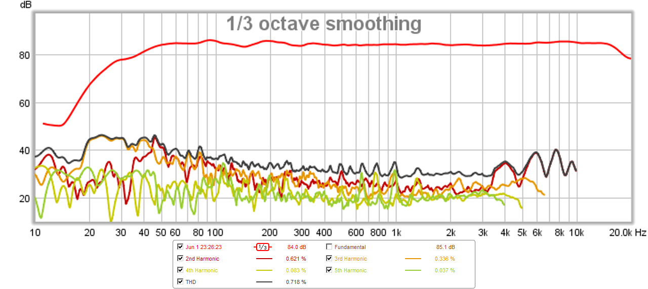
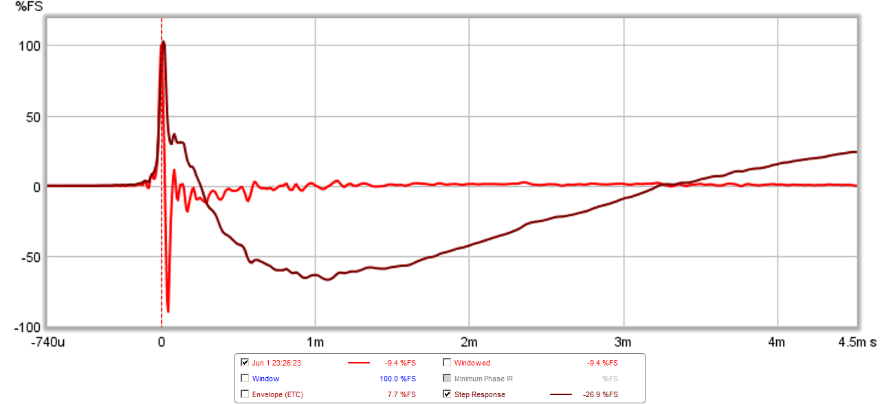
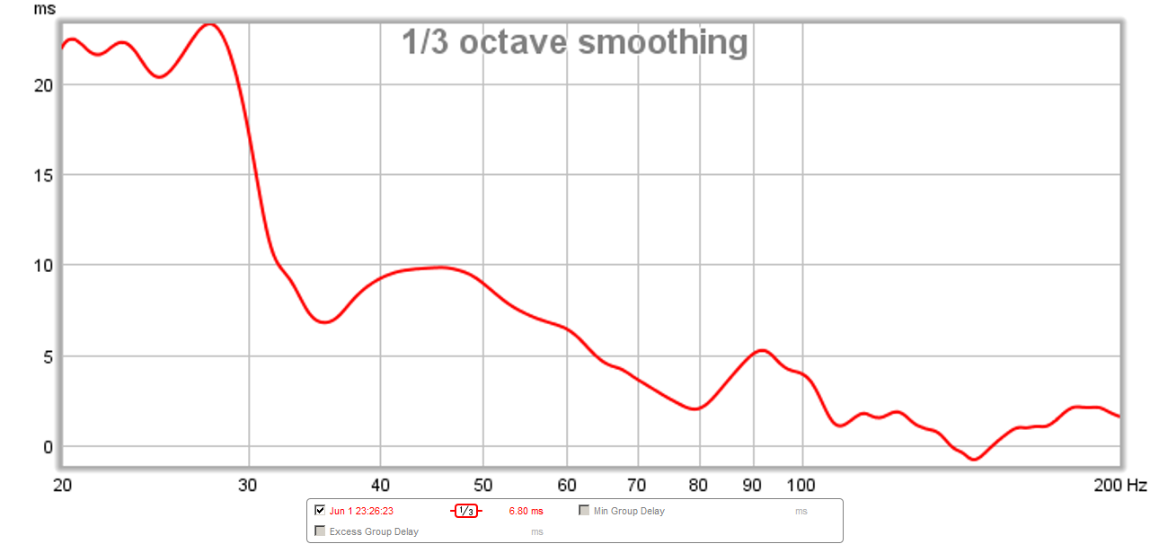
Here is where it stands right now:
SPL and phase (f3 is 41Hz):
Harmonic distortion:
Impulse and Step Response:
Group Delay:
After a much longer listening session, I am still liking what I hear and plan on locking it down for a while. Simply unplug the USB programming cable from the miniDSP.
Here is where it stands right now:
SPL and phase (f3 is 41Hz):
Harmonic distortion:
Impulse and Step Response:
Group Delay:
Attachments


I find that songs with deep bass lines I can hear the bass distortion too much with no HPF on the woofer.
Can you please share some names of such tracks? At what SPLs?
Headshots and Caramel, from Suzanne Vega's Nine Objects of Desire. Many speakers have a hard time with the bass line from these two songs. Playing at about 88 to 91dB.
I find that songs with deep bass lines I can hear the bass distortion too much with no HPF on the woofer. Applying a -12dB/octave BW HPF at 29Hz really cleans up the excessive cone flap and distortion with +5ms hit to the group delay at 45hz.....
If interested in testing find in the zip folder a a FIR filter that neutralize phase for exactly a BW2 29Hz HP. If you play back with JRiver and load it as shown picture one then you can toggle on/off phase turn for that filter on the fly while playing music. As the 29Hz IRR filter is on all time in miniDSP you would have the frequency energy low cut all time but decay of impulse response is very different see at picture two, and picture three is group delay repair when both filters are in a soundcard loop. Filter is made in Rephrase v0.9.9 and is only targeted at 44,1kHz so setup system in that mode and play only 44,1kHz tracks, suggest too run soundcard with WASAPI exclusive mode or ASIO if available.
Another scenario you could turn off 29Hz BW2 HPF in miniDSP and then toggle between following tests. In the zip folder there is 10 other IR as WAV files neat for testing HP filters on the fly in JRiver convolution plugin. They all 29Hz HP in 5 IRR and 5 FIR filters set as BW2/LR2/LR4/LR8/LR16. Play music and shift the filters on the fly to listen and watch their behaviors 🙂.
Attachments


Last edited:
Byrtt,
Thanks for that - I will need to buy Jriver - looks like it is a great program. I ran out of my free 30 day trial a year ago 😀
Excellent result with FIR high pass filter though to get that GD way back down.
Thanks for that - I will need to buy Jriver - looks like it is a great program. I ran out of my free 30 day trial a year ago 😀
Excellent result with FIR high pass filter though to get that GD way back down.
Passive XO revisited with Dagger
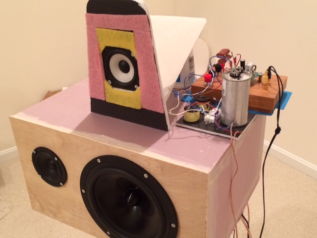
I had a TG9FD already mounted in a short vented aperiodic TL, so I put that on top of the sealed RS225-8 and connected the passive BW1 crossover that Byrtt designed (3.65mH & 57uF with 5R+5R padding on 10F/8424). The bezel of the 10F is round and I already had a rebated square bezel Dagger so I thought I would try the TG9FD first. Byrtt's recommendation was to place the HF unit 3inches behind the LF unit. The sensitivity of the TG9FD is not as high as the 10F, so the that was off. The acoustic XO was way too high with the RS225 having too much contribution above 1kHz such that the XO ended up near 1.2kHz. So I added a 2.5mH coil (1ohm series resistance) to the LF driver and this seems to pull the XO down to maybe 800Hz. Anyhow, here is the setup and the measurements.
Measured frequency response and acoustic xo plot, there is a downward tilt of about 4 to 5 dB from 50hz to 15kHz - which I think many people prefer. This would probably go away with a higher sensitivity 10F (light grey is active 10F FAST system):

Measured absolute phase:

Measured impulse and step response (pretty nice) - the 3 inch setback seems to have done the trick with the time alignment:
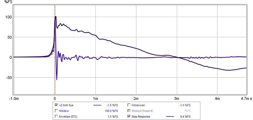
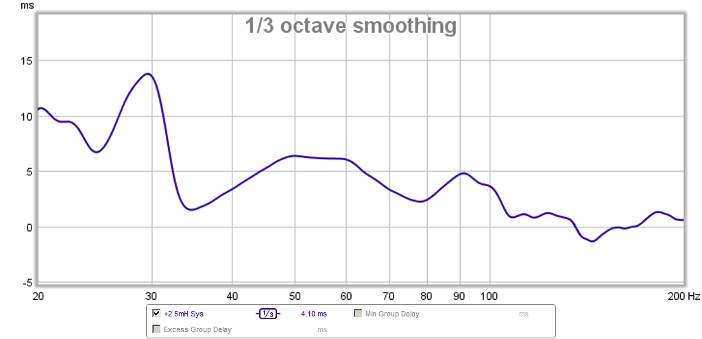
Here is the measured group delay - very nice at under +/-3ms from 35Hz and above:
I am listening to it right now and it sounds pretty good. The bass is surprisingly good for a sealed box without any Linkwitz transform. Will report back later with more listening impressions.
I had a TG9FD already mounted in a short vented aperiodic TL, so I put that on top of the sealed RS225-8 and connected the passive BW1 crossover that Byrtt designed (3.65mH & 57uF with 5R+5R padding on 10F/8424). The bezel of the 10F is round and I already had a rebated square bezel Dagger so I thought I would try the TG9FD first. Byrtt's recommendation was to place the HF unit 3inches behind the LF unit. The sensitivity of the TG9FD is not as high as the 10F, so the that was off. The acoustic XO was way too high with the RS225 having too much contribution above 1kHz such that the XO ended up near 1.2kHz. So I added a 2.5mH coil (1ohm series resistance) to the LF driver and this seems to pull the XO down to maybe 800Hz. Anyhow, here is the setup and the measurements.
Measured frequency response and acoustic xo plot, there is a downward tilt of about 4 to 5 dB from 50hz to 15kHz - which I think many people prefer. This would probably go away with a higher sensitivity 10F (light grey is active 10F FAST system):
Measured absolute phase:
Measured impulse and step response (pretty nice) - the 3 inch setback seems to have done the trick with the time alignment:
Here is the measured group delay - very nice at under +/-3ms from 35Hz and above:
I am listening to it right now and it sounds pretty good. The bass is surprisingly good for a sealed box without any Linkwitz transform. Will report back later with more listening impressions.
Attachments


Last edited:
- Home
- Loudspeakers
- Full Range
- 10F/8424 & RS225-8 FAST / WAW Ref Monitor