It does sound SWEEEET! 🙂
The miniDSP analogy holds because "it's like a box of chocolates, you never know what kind of XO you will need."
The miniDSP analogy holds because "it's like a box of chocolates, you never know what kind of XO you will need."
Another thing you might try, is to target a BW1 on the woofer for 2-3 octaves past the crossover and then roll it off much steeper in the breakup region. Sims show it cleaning up the little phase problems in the treble and it starts getting the breakup down where it should be.
This may or may not effect the SR, but it should help if you find the breakup objectionable. Try listening to the RS225 on it's own with the xo attached. This'll help you pinpoint issues with the sound.

This may or may not effect the SR, but it should help if you find the breakup objectionable. Try listening to the RS225 on it's own with the xo attached. This'll help you pinpoint issues with the sound.
THis is actually what it would look like with your current sealed mid enclosure. This is with with no xo on 10f and delay added to the woofer.
The delay to the woofer had to change from -.13 to -.22 msec. for everthing to work. You can see what the steeper roll off and the additional delay does to the phase in the woofers stop band, but it's basically unchanged around the crossover.

The delay to the woofer had to change from -.13 to -.22 msec. for everthing to work. You can see what the steeper roll off and the additional delay does to the phase in the woofers stop band, but it's basically unchanged around the crossover.
SATX,
I have to delay the 10F *AFTER* the RS225. Are you saying that the RS225 has to be delayed so that it after the the 10F? That seems non-intuitive as usually the HF has to be stepped back from the front baffle for time alignment. But hey, maybe that is why my phase doesn't look as good as your predictions?
I have to delay the 10F *AFTER* the RS225. Are you saying that the RS225 has to be delayed so that it after the the 10F? That seems non-intuitive as usually the HF has to be stepped back from the front baffle for time alignment. But hey, maybe that is why my phase doesn't look as good as your predictions?
Exactly. Weird I know. Usually the mid/tweeter would need delay to align it with the woofer.
In the sims, I have the woofers z axis set at 18mm behind the mid, which should be in the ballpark for what you physically have with your build. That's assuming that the center of the 10f is 12mm and the dayton is 30mm. Not perfect, I'm sure but maybe close.
When I delay the mid by -.018 msec and leave the woofer at 0 I get results that look a lot like what you have been getting. I assume that delaying the woofer will bring it around as far a degrees of phase goes. At least that's what it appears to do. Now, how will this work in practice? I have no idea because you would think that the woofer would just get more out of phase because the sound waves have even more different arrival times.
I'd just try it if you can, because delaying the woofer is what seems to fix everything. Along with eqing the woofer's response @950 to hit BW1 target @350
Yeah, try it and report back if you have time. I believe I mentioned that it was odd when I first outlined how I got those results a few pages back. If it doesn't work, then extending the 10f response with an appropriate enclosure and crossing BW1 allowed for no delay whatsoever. I assume this would also work the same if you wanted to roll off the woofer at the high end though I didn't model that with the ported box.
Did you still want me to model the ported box to see if a port will fit?
Did you still want me to model the ported box to see if a port will fit?
Did you still want me to model the ported box to see if a port will fit?
Yes, thanks.
1.5l, lined enclosure, fb=90hz, port=1.125"Dx5.25"L. This will keep port airspeed in check up to xmax. Tuning to 90 looks better overall than 80 and will give you more sensitivity above tuning so will allow you to cross a bit higher.
Because you're crossing the driver above tuning you could probably reduce the size of the port and not worry about airspeed. .75"Dx2"L will give the same tuning but airspeed is out of control without the crossover. If you use winisd you can model in the crossover, but I'm using something else.
I've heard that you can place the port right behind the driver and it'll be ok, but I've never tried it. Otherwise, I don't know where else it could go with that cone shape you're using.
Also, remember that if you're planning to switch to passive xo then the tuning will probably need to be raised slightly to keep the same response. This is because of the inductance and resistance of the components affecting the drivers parameters.
Stuffing the port lightly will also give you an approximate aperiodic response, so you could try it both ways.
Test BW1 @225Hz and LF Delay
So here are the results of the test with 0.22ms delay applied to the LF driver vs the HF driver. First the good news: applying the 3 PEQ's to the RS225 as SATX suggested and using the BW1 @225Hz filter on the RS225 *amd* a BW1 @350Hz on the 10F/8424 seems to have put the acoustic XO at exactly 350Hz. This is good because it helps to clean up and reduce the cone breakup from the RS225 getting into the mids and treble. Also being able to apply the 350Hz BW1 high pass on the 10F was essential to reduce cone excursion and intermodulation distortion due to letting the HF driver flap in the breeze at lower frequencies. I should mention that absolutely no EQ was applied to the 10F for any of these cases - a remarkably naturally flat response for driver/Dagger combination.
Cases examined:
(a) 0.22ms delay applied to LF only with (-) polarity on LF driver
(b) 0.22ms delay applied to LF only with (+) polarity on LF driver
(c) 0.22ms delay applied to HF only with (+) polarity on LF driver
(d) 0.22ms delay applied to HF only with (-) polarity on LF driver
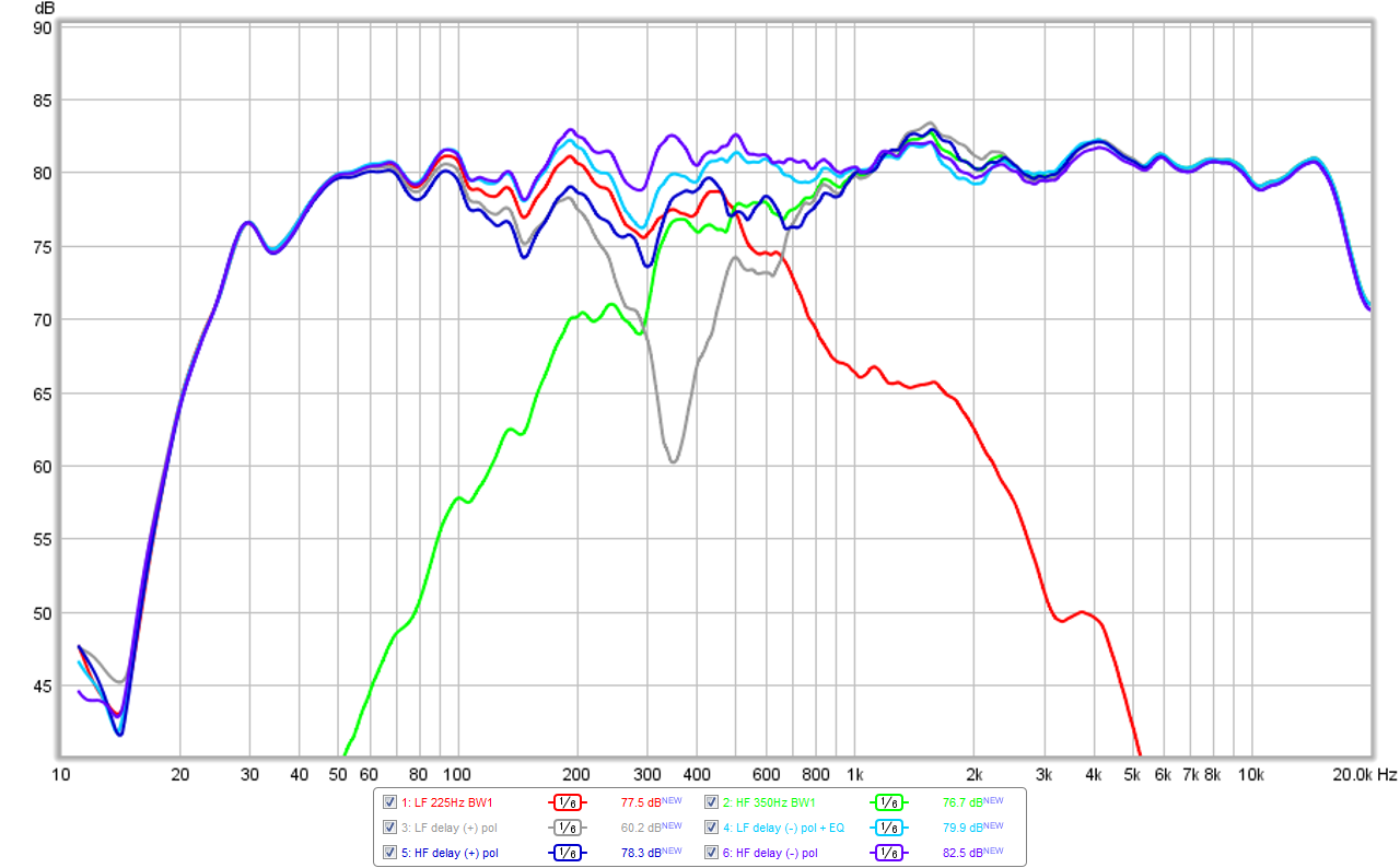
Here is an overall plot of the acoustic XO responses for all the cases - it gets very interesting and I am still at a loss as to what is going on because the phase tracking improves but the SR degrades - shouldn't they concurrently track? For case (b) (grey trace) there is a clear cancellation dip at exactly 350Hz, which tells me that the 225Hz and 350Hz XO settings is providing the ideal 350Hz acoustic XO point. This case is no good for a number of reasons so will not be explored in detail with Phase or IR/SR as will be shown for other cases.
Measured acoustic XO plot - light blue is case (a), dark blue is case (c), indigo is case (d); for case (a) I had to apply a -4dB Q=1 peak cut at the 350Hz XO freq to reduce the summation bump for this case. Usually, a BW1 does not have a summation bump, which was as predicted with cases (c) and (d):
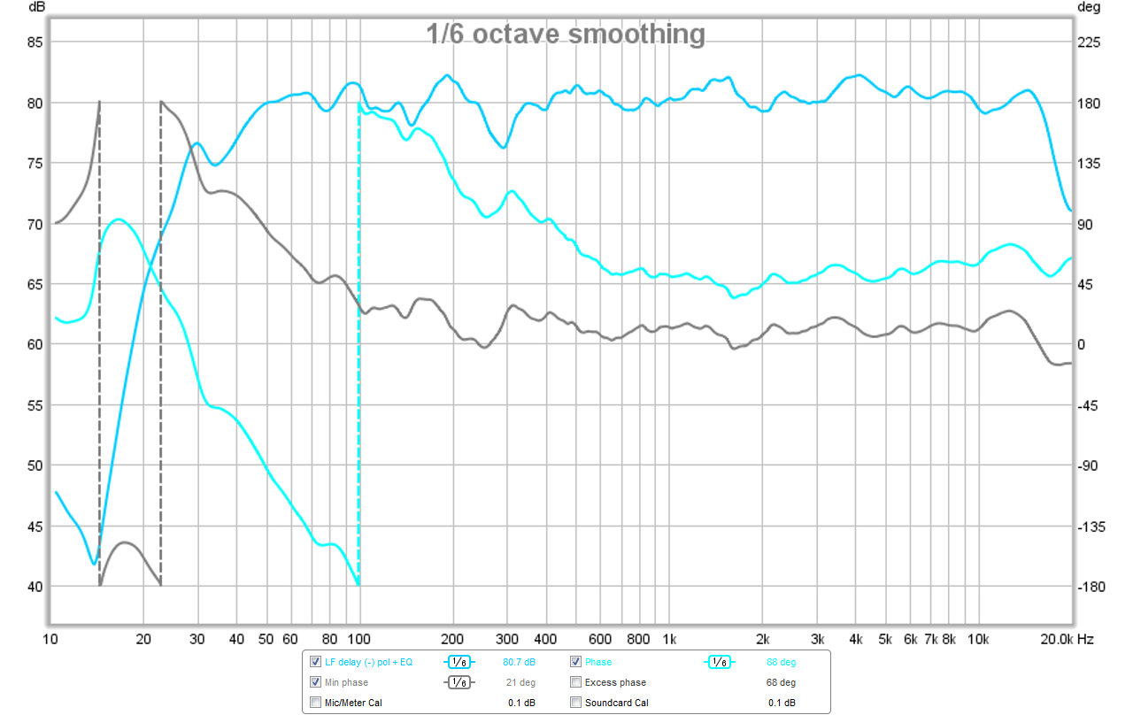
Here is the phase for the delay applied to LF driver with (-) polarity on LF driver - case (a):
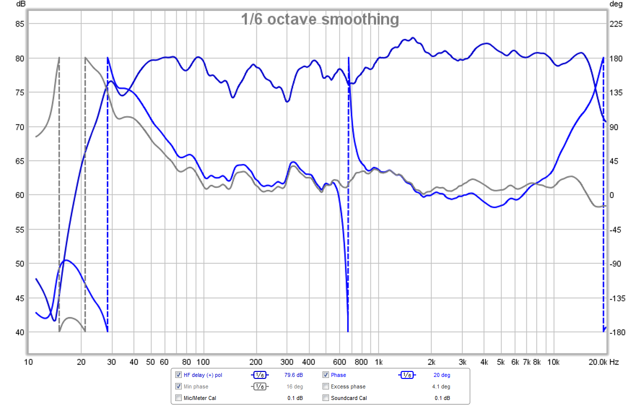
Here is the phase for the delay applied to HF driver with (+) polarity on LF driver; not sure what is going on near 750Hz, other than it may correspond to the sharp peak cut PEQ applied to the LF driver to get it to behave - case (c):
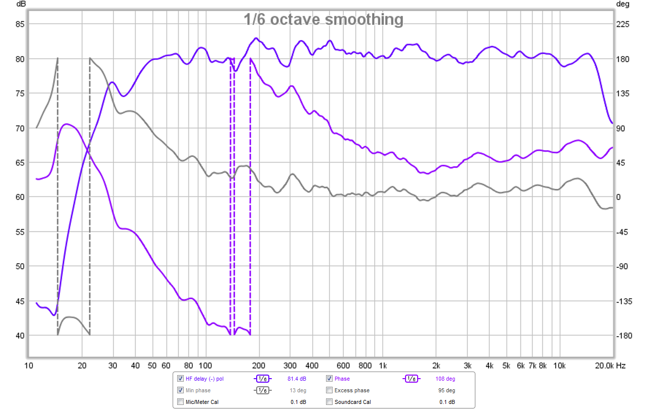
Here is the phase for the delay applied to HF driver with (-) polarity on LF driver - case (d):
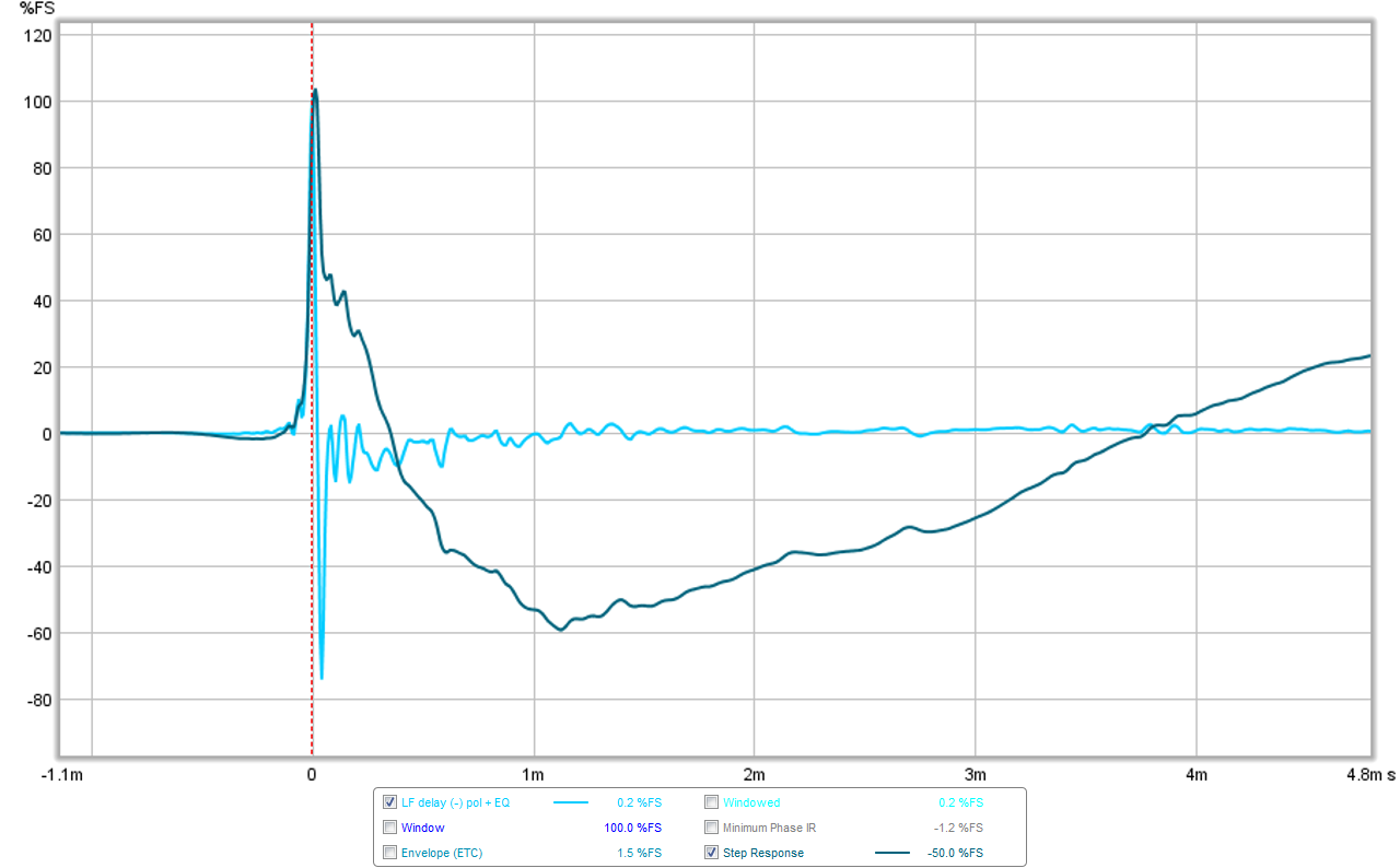
Here is the impulse/step response for the delay applied to LF driver with (-) polarity on LF driver - case (a):
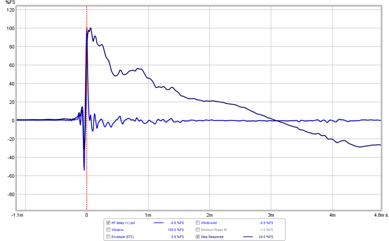
Here is the impulse/step response for the delay applied to HF driver with (+) polarity on LF driver - case (c):
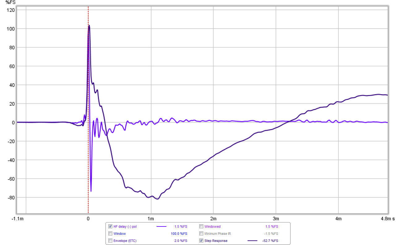
Here is the impulse/step response for the delay applied to HF driver with (-) polarity on LF driver - case (d); note that this looks very similar to case (a):
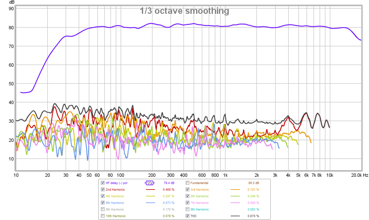
I got to listen to the three cases briefly with just two test tracks, so not extensive by any means but here is the subjective assessment. Cases (a), (c), and (d) all sound very close and imaging is excellent. The time alignment of case (c) sounds slightly better when presented with sharp percussion instruments followed with kick, like kick drums or stand-up plucked bass. They all sound quite clean with low distortion now that the HF driver has a high pass filter, as can be seen here (at low 80dB SPL it is not a hard test but there are no anomalies); shown here is HD for case (d):
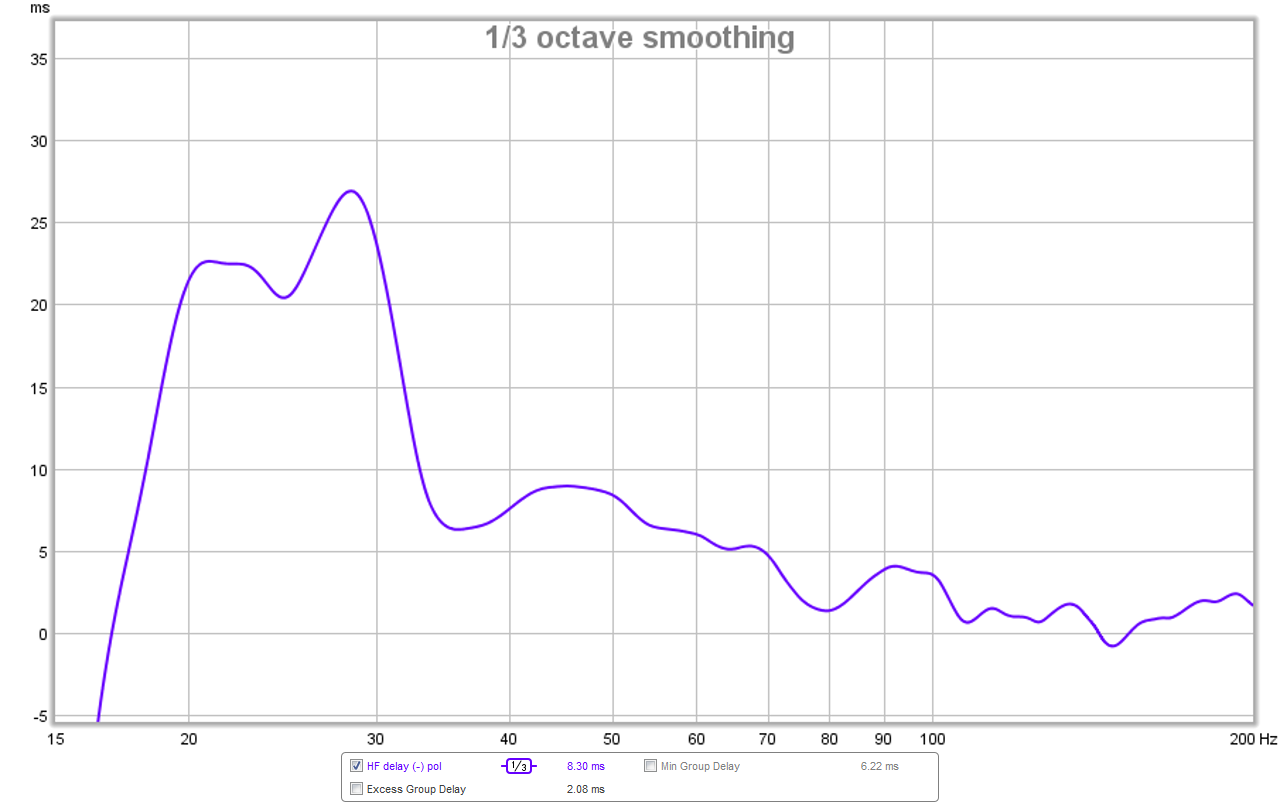
And group delay for all cases pretty much look like this, although slightly worse for case (a) since LF delayed before HF; shown here is GD for case (c) - under 8ms above 35Hz which is great actually:
Having said all this, I think at this point, the sound quality of case (d) seems to have a slight edge over the other cases. I will need more time to listen though before final verdict. I think a major accomplishment is getting the acoustic XO to behave and sit at 350Hz, and this did not require a larger bass reflex alignment on the 10F. This is great as I don't want to do foam core surgery on these boxes 🙂
So here are the results of the test with 0.22ms delay applied to the LF driver vs the HF driver. First the good news: applying the 3 PEQ's to the RS225 as SATX suggested and using the BW1 @225Hz filter on the RS225 *amd* a BW1 @350Hz on the 10F/8424 seems to have put the acoustic XO at exactly 350Hz. This is good because it helps to clean up and reduce the cone breakup from the RS225 getting into the mids and treble. Also being able to apply the 350Hz BW1 high pass on the 10F was essential to reduce cone excursion and intermodulation distortion due to letting the HF driver flap in the breeze at lower frequencies. I should mention that absolutely no EQ was applied to the 10F for any of these cases - a remarkably naturally flat response for driver/Dagger combination.
Cases examined:
(a) 0.22ms delay applied to LF only with (-) polarity on LF driver
(b) 0.22ms delay applied to LF only with (+) polarity on LF driver
(c) 0.22ms delay applied to HF only with (+) polarity on LF driver
(d) 0.22ms delay applied to HF only with (-) polarity on LF driver
Here is an overall plot of the acoustic XO responses for all the cases - it gets very interesting and I am still at a loss as to what is going on because the phase tracking improves but the SR degrades - shouldn't they concurrently track? For case (b) (grey trace) there is a clear cancellation dip at exactly 350Hz, which tells me that the 225Hz and 350Hz XO settings is providing the ideal 350Hz acoustic XO point. This case is no good for a number of reasons so will not be explored in detail with Phase or IR/SR as will be shown for other cases.
Measured acoustic XO plot - light blue is case (a), dark blue is case (c), indigo is case (d); for case (a) I had to apply a -4dB Q=1 peak cut at the 350Hz XO freq to reduce the summation bump for this case. Usually, a BW1 does not have a summation bump, which was as predicted with cases (c) and (d):
Here is the phase for the delay applied to LF driver with (-) polarity on LF driver - case (a):
Here is the phase for the delay applied to HF driver with (+) polarity on LF driver; not sure what is going on near 750Hz, other than it may correspond to the sharp peak cut PEQ applied to the LF driver to get it to behave - case (c):
Here is the phase for the delay applied to HF driver with (-) polarity on LF driver - case (d):
Here is the impulse/step response for the delay applied to LF driver with (-) polarity on LF driver - case (a):
Here is the impulse/step response for the delay applied to HF driver with (+) polarity on LF driver - case (c):
Here is the impulse/step response for the delay applied to HF driver with (-) polarity on LF driver - case (d); note that this looks very similar to case (a):
I got to listen to the three cases briefly with just two test tracks, so not extensive by any means but here is the subjective assessment. Cases (a), (c), and (d) all sound very close and imaging is excellent. The time alignment of case (c) sounds slightly better when presented with sharp percussion instruments followed with kick, like kick drums or stand-up plucked bass. They all sound quite clean with low distortion now that the HF driver has a high pass filter, as can be seen here (at low 80dB SPL it is not a hard test but there are no anomalies); shown here is HD for case (d):
And group delay for all cases pretty much look like this, although slightly worse for case (a) since LF delayed before HF; shown here is GD for case (c) - under 8ms above 35Hz which is great actually:
Having said all this, I think at this point, the sound quality of case (d) seems to have a slight edge over the other cases. I will need more time to listen though before final verdict. I think a major accomplishment is getting the acoustic XO to behave and sit at 350Hz, and this did not require a larger bass reflex alignment on the 10F. This is great as I don't want to do foam core surgery on these boxes 🙂
Attachments
-
 07-10f-rs225-fast-bw1-225hz-hf-delay-negative-pol-ir-sr.png93.8 KB · Views: 738
 -
 06-10f-rs225-fast-bw1-225hz-hf-delay-positive-pol-ir-sr.png89.3 KB · Views: 737
 -
 05-10f-rs225-fast-bw1-225hz-lf-delay-negative-pol-ir-sr.png89.7 KB · Views: 771
 -
 04-10f-rs225-fast-bw1-225hz-hf-delay-negative-pol-phase.png160 KB · Views: 768
 -
 03-10f-rs225-fast-bw1-225hz-hf-delay-positive-pol-phase.png167.3 KB · Views: 773
 -
 02-10f-rs225-fast-bw1-225hz-lf-delay-negative-pol-phase.png145.7 KB · Views: 776
 -
 01-10f-rs225-fast-bw1-225hz-polarity-study-xo.png169.2 KB · Views: 955
 -
 11-10f-rs225-fast-bw1-225hz-hf-delay-negative-pol-hd.png296.3 KB · Views: 740
 -
 10-10f-rs225-fast-bw1-225hz-hf-delay-negative-pol-gd.png69.2 KB · Views: 740
Last edited:
So here are the results of the test with 0.22ms delay applied to the LF driver vs the HF driver. First the good news: applying the 3 PEQ's to the RS225 as SATX suggested and using the BW1 @225Hz filter on the RS225 *amd* a BW1 @350Hz on the 10F/8424 seems to have put the acoustic XO at exactly 350Hz. This is good because it helps to clean up and reduce the cone breakup from the RS225 getting into the mids and treble. Also being able to apply the 350Hz BW1 high pass on the 10F was essential to reduce cone excursion and intermodulation distortion due to letting the HF driver flap in the breeze at lower frequencies. I should mention that absolutely no EQ was applied to the 10F for any of these cases - a remarkably naturally flat response for driver/Dagger combination.
Cases examined:
(a) 0.22ms delay applied to LF only with (-) polarity on LF driver
(b) 0.22ms delay applied to LF only with (+) polarity on LF driver
(c) 0.22ms delay applied to HF only with (+) polarity on LF driver
(d) 0.22ms delay applied to HF only with (-) polarity on LF driver
Here is an overall plot of the acoustic XO responses for all the cases - it gets very interesting and I am still at a loss as to what is going on because the phase tracking improves but the SR degrades - shouldn't they concurrently track? For case (b) (grey trace) there is a clear cancellation dip at exactly 350Hz, which tells me that the 225Hz and 350Hz XO settings is providing the ideal 350Hz acoustic XO point. This case is no good for a number of reasons so will not be explored in detail with Phase or IR/SR as will be shown for other cases.
Wow, thanks for posting all the results X!
You did many things differently than I did in the simulations, so most of your results appear different than what I got.
First of all I flip polarity on the "tweeter", the woofer is usually fixed. I doubt it makes any difference, but hey.
It looks like you maybe applied a bit too much cut @950 on the rs225. Notice the dip in the stop band there. What I did is cut until the roll off hit's your BW1 @350 target. This required a light cut on the 10f @ 1500 to have a smoothed summed response. THis is because my sims showed a little peaking in the 10f response on your baffle there, but maybe yours is different because I had to guess your dimensions and driver placement a little.
Now to the bigger stuff that's really going to change how things look-
When you apply a crossover to the 10f you alter the phase a lot so the woofer delay is no longer needed or accurate. This is also why you now have to reverse polarity, because you've created a phase shift. The problem is that you don't appear to have a BW1@350 slope anymore. It looks more like second order slopes to me, and that's fine if you're ok with that, but I thought you were trying to hit BW1 targets.... In fact in my sim I hit a perfect LR2@350 with a BW1@350 xo. The driver naturally needs to extend lower if you want BW1 slopes if that matters to you.
Once again, the fact that you applied a xo to the 10f changes everything. When I applied the xo with the ported box sim, I removed all delay for the best results. This is because of the xo not the port.
Also, you applied -.22 when the number was supposed to be -.13. The -0.22 msec delay on the woofer was only for the extreme cut on the rs225 breakup that I posted yesterday. This is where you have a BW1 up to 2k and then it rolls of faster. Of course none of this matters because of the xo on the 10F
If you're were not doing this then the delay should be set at -0.13 msec with both drivers with positive polarity and no crossover on the 10f.
I don't have a ton of faith that applying additional delay to the woofer is the right way to do things, but I was hoping to see if your measured results correlated with the simulated results. Unfortunately, you changed the conditions too much to know.
Anyways, all the instructions, numbers and explanations are in my previous posts with the plotted responses.
Thanks sharing satx and xrk971,
Great trials but if transient perfect response is goal run all drivers in same polarity, correct me if wrong below 🙂.
Transient perfect response from IRR filters then all drivers always need same polarity this is for BW1 in two way and three way the filler driver with LR2 (B&O) and Steen Duelund filler with LR4 filters.
Say this because as i see it if running BW1 with one driver flipped then why not use BW2/4 or LR2/4, in post 274 showed live square wave measurements for BW2 LR2/4 and flipping a driver in BW1 means going to ala same look http://www.diyaudio.com/forums/full...-rs225-8-fast-ref-monitor-28.html#post4336282.
I will try the 0.13ms and no XO on the 10F just to see if it matches your predictions. I was in a rush doing this and forgot the delay was only 0.13ms.
Thanks sharing satx and xrk971,
Great trials but if transient perfect response is goal run all drivers in same polarity, correct me if wrong below 🙂.
Transient perfect response from IRR filters then all drivers always need same polarity this is for BW1 in two way and three way the filler driver with LR2 (B&O) and Steen Duelund filler with LR4 filters.
Say this because as i see it if running BW1 with one driver flipped then why not use BW2/4 or LR2/4, in post 274 showed live square wave measurements for BW2 LR2/4 and flipping a driver in BW1 means going to ala same look http://www.diyaudio.com/forums/full...-rs225-8-fast-ref-monitor-28.html#post4336282.
I agree that same polarity is only way to get transient perfect SR as seen in case (c) above. What is strange is that the phase doesn't appear as smooth.
Actually, using your settings above, with a crossover applied to both drivers, I'm able to recreate what you have posted here. So it appears that the simulation is fairly accurate.
If you decide to try using the settings that I outlined before, you should get very similar results to what is predicted. I don't know if this will necessarily be better or not though because I can't predict SR, GD, etc.
And BTW, at least in the sims, which appear to be accurate, phase isn't as good as you think which could be why your SR doesn't look as good as you think it should.
It's also tough to know where you crossover is exactly because of the room reflections in your measurements. In the simulations if appears to be more like 500Hz
I agree that same polarity is only way to get transient perfect SR as seen in case (c) above. What is strange is that the phase doesn't appear as smooth.
The phase probably isn't as smooth because the delay is wrong since you were using my settings with no xo on your speaker with a xo.
SR probably improved because of the same polarity as you Byrtt says
- Home
- Loudspeakers
- Full Range
- 10F/8424 & RS225-8 FAST / WAW Ref Monitor