Export the impulse and one of us can produce the step in arta
You mean export impulse response as wav?
You mean export impulse response as wav?
Probably txt that can be converted into CSV and imported
I run Arta in demo mode (free), it can plot the step response
I've never done it with imported data, but I'm pretty sure it can do that
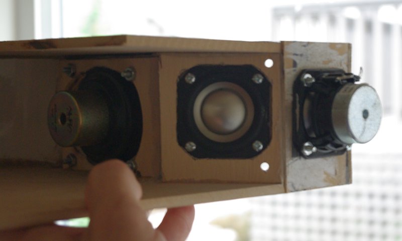
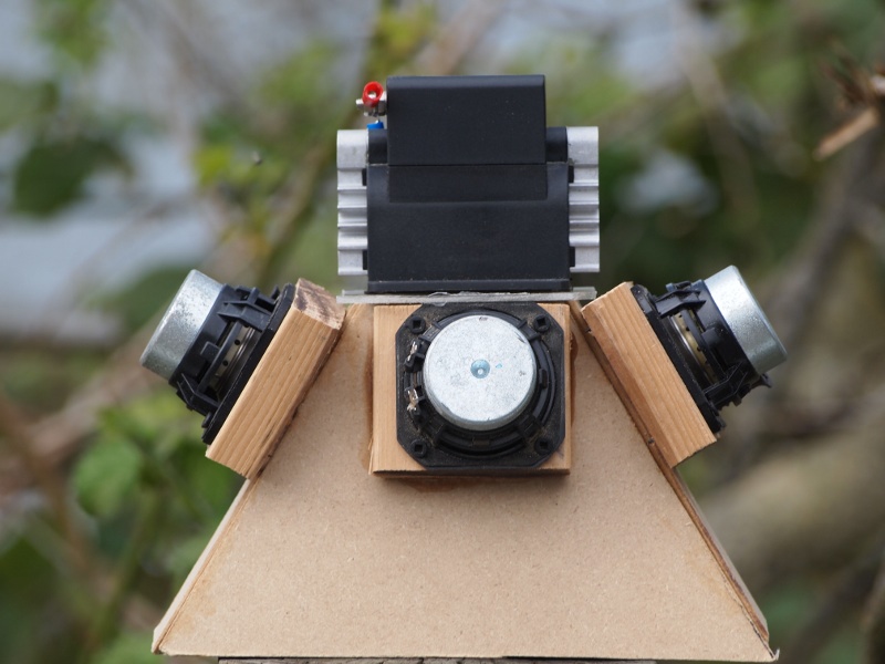
I've tried nearly everything at the apex. Cone drivers, ribbons, domes, compression drivers. Here's some pics of various synergy horns I've built. Nearly all of them are documented on diymobileaudio.com or diyaudio.com
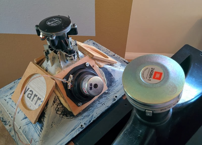
I tried a cone at the apex using a Faital 3FE20. Can't find the pics right now. It sounded ok but a compression driver sounded better. Measure the cumulative spectral delay and you'll see why the compression driver sounds better.
So it was not so new aymore🙂 The testing with a tractrix is now going on, maybe the different between the conic and tractrix will do better, it looks that way, however I do not like break up cone speakers, it feels so wrong even when sound nice, a very strong motor to control heavy cone do on high frequenties cause breakups.
Compression driver are never be replaceble by a cone one, because of the very very small chambers, what makes it a compression driver. Here she try to make a two way with a tractrix, I will go soon try one myself with the visaton 3 inchers with light cone to see what happens, hope to get it as low as 500 hz for easy crossover.
regards
kees
The 3FE22 (Nd) and 3FE25 (Ferrite) should be coming today.
Woohoo! 🙂
I have a pair of compression drivers (1kHz up) that I could test...
someone now how to see impuls in akabak?
And xrk971 how did you fill in the width and height in the horn?
the part ratio horn width to high in tractrix sheet.
and the numbers you take there 16 values I did see in the script, when you let now I
can test the visaton when I have time.
regards
And xrk971 how did you fill in the width and height in the horn?
the part ratio horn width to high in tractrix sheet.
and the numbers you take there 16 values I did see in the script, when you let now I
can test the visaton when I have time.
regards
Last edited:
someone now how to see impuls in akabak?
And xrk971 how did you fill in the width and height in the horn?
the part ratio horn width to high in tractrix sheet.
and the numbers you take there 16 values I did see in the script, when you let now I
can test the visaton when I have time.
regards
Click iFFT button on top middle once you have freq response calculated. That is inverse FFT of freq which is time.
The width and height are from the Volvotreter spreadsheet - width and height are flipped. Height is the curved panel width at distance x from throat and width is height of horn across flat panels. I will post the curved panel pattern soon. Unless you are handy with cad it is very tricky to make this yourself.
Thanks got it.
And you make it yourselfs so I can also.
I have flip the horn this way in sheet, but if this is oke, I think tractrix is now on wrong site, I do not now how it is implend it then I have to drawn and see.
Yes I can drawn cad, see last picture from hornresp, but need clear data, and sheet make very long ones, mucho time consuming is the biggest problem, not needed in pc world of today...
What is the height and width of your horn? I do mean the bigger one who i did sim, because I have no script for the smaller one to try.
regards
kees
Attachments


Last edited:
I will post the spreadsheet for you when I get to my computer. Ok I forgot you can do 3d sketch up - but can you draw an tractrix curve then flatten it for the 2d cut pattern? It took me a couple days to figure that one out.
I have seen a script somewhere who can flatten, but a tractrix of exp curve i do use thin wood, bent and glue it on a mal, that mal is the conic part of the horn, not so difficult I think.
But I go to sleep, it is here 2.00 hour in the night, and still to warm with our indian summer, I do cool somewhat with cool beer tough..
In picture I let see how I do it, not so difficult, this is a exponentional flare.
regards
kees
But I go to sleep, it is here 2.00 hour in the night, and still to warm with our indian summer, I do cool somewhat with cool beer tough..
In picture I let see how I do it, not so difficult, this is a exponentional flare.
regards
kees
Attachments

175Hz tractrix horn spreadsheet
Here is the spreadsheet with values that I used for the full sized 24 in wide horn with the 5MR450NDY. Scale this by 0.70x and you have the horn used in this thread.
It's the tab called "Rect. Horns by Throat & fc"
Here is the spreadsheet with values that I used for the full sized 24 in wide horn with the 5MR450NDY. Scale this by 0.70x and you have the horn used in this thread.
It's the tab called "Rect. Horns by Throat & fc"
Attachments
Downloading now!
Edit: Is this the dimensions for the flattened faces that are curved?
Edit: Is this the dimensions for the flattened faces that are curved?
Last edited:
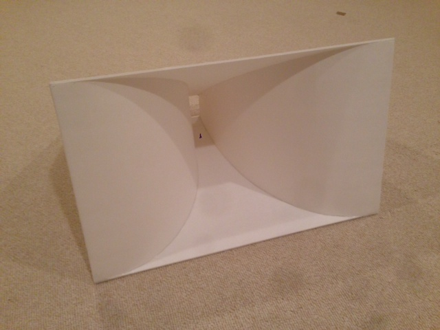
How to build tractrix profile in foam core
In case you missed it, the steps to making the tractrix are detailed starting here:
http://www.diyaudio.com/forums/full-range/259293-prv-5mr450-ndy-fast-applications-post4033907.html
I will get PDF uploaded soon.
In case you missed it, the steps to making the tractrix are detailed starting here:
http://www.diyaudio.com/forums/full-range/259293-prv-5mr450-ndy-fast-applications-post4033907.html
I will get PDF uploaded soon.
Downloading now!
Edit: Is this the dimensions for the flattened faces that are curved?
It is the dimensions for the profile in 3d. The width is actually the width of the flat sides at point x from throat. Height is spacing between curved walls at point x from throat. That is why I made 3d model from this and then made 2d cut pattern.
Cut plan for full scale 175Hz tractrix for 5MR450NDY
Note that these directions are for full scale horn. For 0.70x scale tractrix synergy, scale pdf dimensions by 0.70x and flat panels by 0.70x. The scaling should be such that throat dimensions are 2.00 in x 2.00 in square.
Assuming you are building this using standard 3/16in thick foam core panels. The flat top and bottom panels (before trimming to follow curved walls) are 22.4 in deep x 28.0 in wide. At the centerline of 14.0 in mark of 2.78 in/2 or 1.39 in line on each side of the centerline - this is where the throat will be glued. The mouth is glued tangent to the front edge for the first inch or so.
Start by gluing the throat section along a 3 inch long segment. Then glue a 3 inch segment of the mouth. As the hot melt glue sets, force the remainder of the edges of the curved wall to be flush with the flat panel. The anchoring of the throat and mouth and edges forces the tractrix shape to form automatically. Then add a bead of hot melt glue on inside and outside of joint between curved and flat walls. Repeat for opposite curved wall onto same flat panel.
Once both curved walls are glued onto one flat panel, repeat process by adding the other flat wall and start from throat to mouth, then middle. Note that the dimensions of the throat are the *inside* dimensions so shift foam core accordingly by 3/16in.
Before gluing the curved panels, use a long straight edge and razor to score cuts that just pierce the top layer of paper on the *concave* (outer side of horn wall). Make parallel cuts every 3 to 5 mm spacing perpendicular to horn axis. After cuts are made place scored piece on soft carpeted floor with cuts face up. Use a 4 to 5 in dia cylindrical object to roll on top of panel while gently using hands underneath to bend panel along the curved cylinder a little at a time to form it into a curve - to pre-bend it so it easily forms to the tractrix shape when glued.
Print the pdf to a full scale drawing by using the "Tile" function in Adobe Acrobat. Select the scale so that it prints the final drawing with exactly 1.00 inch shown on the grid. I found that I had to apply a 0.95x scale in Adobe Acrobat to get 1.00 in full scale with most printers.
Thus for the 0.70x scale horn, use a 0.95 x 0.70 = 0.665x scale in the Adobe Acrobat "Tile" print. Then tape the tiles together using the grid marks. Lay the drawing template above foam and use a pen to pierce little holes and leave divet on the foam every inch or so. Now hand sketch the curve on the foam following the divets. Then use a razor to cut following those lines. i find an xacto best for these curved cuts. Go slowly just enough to pierce paper on first cut then slowly apply more pressure. I use 4 to 5 strokes before going through the foam. I find laying foam on Berber carpet makes a great cutting mat.
Good luck!
Attachments
Last edited:
Thanks! That was easy once someone shows you how to do it. 🙂 let me know what you think of the phase I just plotted.
That phase response looks good but I wonder where the 5,6kHz phase wrap comes from. Is that where the the cone starts to fade off and the dust cap starts to dominate perhaps? Have you tried reproducing square waves? It can be done also with demo-ARTA. In spectrum mode after recording the square waves for some time, perhaps using a linear/expo averaging, there is this green button "view time record" that shows the actual wave shape.
By the way, you can look the step response also in REW. Go to "Overlays" button at the top, or Tools/Overlays from the menu. There you can plot the step response. The REW is quite versatile nowadays.
Last edited:
Here is the spreadsheet with values that I used for the full sized 24 in wide horn with the 5MR450NDY. Scale this by 0.70x and you have the horn used in this thread.
It's the tab called "Rect. Horns by Throat & fc"
Thanks for the sheet, I did see the throat is 0.5 x Sd? of how do you take this in account, for my in script I did use Sd (26 cm2) for as you did I have tp halve this, give compression on cone..
Did you scale on a drawnprogram? because when do it is not 175 Hz anymore, is it better to use higher cutoff in stead.
regards
I made the throat diagonal match the dia of the cone Sd. Which geometrically gives something closer to 64% of Sd. This was my attempt at making it as big as possible to allow HF through but not physically larger than active Sd diam.
That phase response looks good but I wonder where the 5,6kHz phase wrap comes from. Is that where the the cone starts to fade off and the dust cap starts to dominate perhaps? Have you tried reproducing square waves? It can be done also with demo-ARTA. In spectrum mode after recording the square waves for some time, perhaps using a linear/expo averaging, there is this green button "view time record" that shows the actual wave shape.
By the way, you can look the step response also in REW. Go to "Overlays" button at the top, or Tools/Overlays from the menu. There you can plot the step response. The REW is quite versatile nowadays.
The wrap comes from me trying to fill a dip which I believe is caused by either the cone breakup mode begining or the weak motor getting affected by pressure feedback from horn driver chamber. I am not going to worry about it too much I think we are expecting too much out of the little Vifa which has done an amOng job of being front horn loaded given the weak motor and floppy suspension.

Yes, there is a slight constriction before expanding - it is important to keep. I have that captured in the sim. The construction will have a very slight angle to constrict after throat. Thanks for asking as I forgot to mention this is post 94 above. When gluing the initial throat anchoring angle the wall or taper to get the constriction. Maybe 1.5 degrees or so - not much.
Last edited:
- Home
- Loudspeakers
- Multi-Way
- Presenting the Trynergy - a full range tractrix synergy.