...Is my amp playing tricks on me?
It shouldn't, but how about volume dial is it positioned as usual 😛
Thanks for the updates. Agree that some things that catch our attention and sound interesting at first don't stand the test of time.
It shouldn't, but how about volume dial is it positioned as usual 😛
I did look into that, as some house cleaning has been responsible for moved dials before. It seemed what I have now is a bit of an intermittent problem, that's why I mentioned the ~27 year old amp (last serviced about 4 years ago).
Quite a while ago, I stumbled over one of my own pictures in a Google search. It turned out it came from Pinterest and it pointed back at this thread. I decided to join to see what more I could find. Pinterest often turns up more interesting results than a Google search.
Eventually I've made my own collection of the Two Towers. Not nearly all pictures are included but it does provide a nice overview.
Eventually I've made my own collection of the Two Towers. Not nearly all pictures are included but it does provide a nice overview.
I enjoyed a wonderful afternoon of music, just playing random stuff.
More and more I'm convinced, it's all about the balance... at the ears...
Which means one should look at what the room adds, at the ears...
It also convinced me I prefer Stereo over Mono, though stereo does need work for me to get the proper tonal balance.
I should get off the couch and start measuring at ear positions, I will, in due time. Work is keeping me busy lately,
I hope that will change sometime soon.
Last edited:
I know, getting off the couch is hard sometimes! 😉
I forgot, did you buy the subwoofer drivers yet? That discussion was a while back, and I forgot if you bought the drivers or still tinkering with the design.
I'm sure you also considered a design close to your initial tower approach. I did. It's been running around my head for a while, and I stumbled onto an article about the BG Radia BGX-4850 In-Wall Subwoofer and I thought it could work well in your living room, being in-wall and not visually obtrusive.
Like I said, I'm sure you thought about this design as well... but maybe not about aiming the mini subs at each other.
Personally I would love to try something like that. Alas that's not in the cards for me 🙂.
That will never pass the home committee.
I do have 2x Scan Speak 30W, waiting for me to build them a home. It will probably turn out like the sketches I showed earlier:

That is what did pass the beauty commission, to replace the black benches currently seen in our room:

(photo taken at the get together with BYRTT and xrk971)
I'm still under strict orders to not add anything more. 😱
At least my devious plan to "reserve" the space for future sub additions worked out! It's no coincidence these benches ended up there after I moved my stereo equipment. 😉
Got to make compromises, how many of you are allowed to have giant speakers like this out in the living room? I consider myself a lucky bastard.
I'll just have to make this work. I'm not even that flexible in placement.
That will never pass the home committee.
I do have 2x Scan Speak 30W, waiting for me to build them a home. It will probably turn out like the sketches I showed earlier:
That is what did pass the beauty commission, to replace the black benches currently seen in our room:
(photo taken at the get together with BYRTT and xrk971)
I'm still under strict orders to not add anything more. 😱
At least my devious plan to "reserve" the space for future sub additions worked out! It's no coincidence these benches ended up there after I moved my stereo equipment. 😉
Got to make compromises, how many of you are allowed to have giant speakers like this out in the living room? I consider myself a lucky bastard.
I'll just have to make this work. I'm not even that flexible in placement.

Many people argue about line arrays and comb filtering. In a reply on a different thread I've put some graphs on display arguing how I look at this problem. All to often I see center to center spacing as being the cause of the comb pattern. That's not how I look at it. Even with plenty of point sources we would still get combing. How's that? the only spacing that really matters if a source starts combing is the spacing from one's ear to the array. 😱
Controversial thoughts? Let's copy my post from that thread:
Actually, at 5400 Hz, one wavelength would be 2.5". I did not check that before, you simply took one wavelength as the cause of combing. So ear against the array would have all drivers sum in this case 🙂.
Still, my argument holds up. You can't name a frequency and state it will start combing at that frequency based on center to center driver distance. As we'd need to know the distance from the array as well as it's length.
Lets put it into a graph:

Here I've drawn waves at a listening distance of 2.5 m, each driver gets a wave and the dotted lines behind the "blue wave" are 1.25" behind, meaning out of phase at 5400 Hz.
Where the continuous blue line touches the dotted line behind it is were a driver is out of phase with another driver. On our design axis, in line with the bottom diver, we see that none of the other drivers is completely out of phase with another driver. This is the worst case scenario with this array at 5400 Hz, be it, at a distance of 2.5 meter.
(they are actually within a quarter wave distance, and still summing positively, directly in line with the bottom driver)
Let's examine closer to the array:

See how at 1 meter distance the situation has changed? The upper most driver's wave front is out of phase with the bottom driver (check it's dotted line) at our design axis.
The rest of them still sum.
This shows that driver spacing does have an influence on the resulting combing. But not like you claimed it would. If I had more drivers in between the top and bottom one, thus spaced closer together, the top driver would still be out of phase with the bottom one at 1M distance. However the transition would be more smoothed out due to having multiple drivers sum and subtract. Getting closer in behaviour to a continuous array.
But not in any way like you said it would, concluded from that center to center spacing.
At 2.5 meter none of the drivers would be out of phase with another on our design axis at 5400 Hz. This does not depend on the number of drivers in our short array here. It is determined by the distance from the array and the length of the array. More drivers packed closer together would fill in the spots in between, kind of like anti-aliasing. Getting you closer to a seamless array. Now make it floor to ceiling and assume the floor and ceiling are reflective.
Posted: here.
So would it help if one was to add more smaller drivers at ever closer center to center spacing? Yes. But not like conventional wisdom might tell us. It would generate a more seamless transition, getting us closer to the ideal infinite array. However the listening distance to that array would still see patterns add and subtract, just like in our lesser packed array. Creating that drop in SPL at ever higher frequencies.
This is the reason I would not shade a floor to ceiling array. Only a finite one if it can't use the floor or ceiling to extend it's length.
Some people actually PM-ed me and figured out what I'm saying here. If you look at ra7's measurements at different distances from the array you can see the same trends, as the visual combing in his graphs moves up in frequency the further you move away from the array.
It's all still a compromise, the ideal would certainly be a seamless array. However it is a compromise I'm willing to make.
Disclaimer: the center to center spacing in this example is based on the proposal in the thread I posted on. My own center to center spacing is different, slightly larger at 85.5 mm.
Controversial thoughts? Let's copy my post from that thread:
Actually, at 5400 Hz, one wavelength would be 2.5". I did not check that before, you simply took one wavelength as the cause of combing. So ear against the array would have all drivers sum in this case 🙂.
Still, my argument holds up. You can't name a frequency and state it will start combing at that frequency based on center to center driver distance. As we'd need to know the distance from the array as well as it's length.
Lets put it into a graph:
Here I've drawn waves at a listening distance of 2.5 m, each driver gets a wave and the dotted lines behind the "blue wave" are 1.25" behind, meaning out of phase at 5400 Hz.
Where the continuous blue line touches the dotted line behind it is were a driver is out of phase with another driver. On our design axis, in line with the bottom diver, we see that none of the other drivers is completely out of phase with another driver. This is the worst case scenario with this array at 5400 Hz, be it, at a distance of 2.5 meter.
(they are actually within a quarter wave distance, and still summing positively, directly in line with the bottom driver)
Let's examine closer to the array:
See how at 1 meter distance the situation has changed? The upper most driver's wave front is out of phase with the bottom driver (check it's dotted line) at our design axis.
The rest of them still sum.
This shows that driver spacing does have an influence on the resulting combing. But not like you claimed it would. If I had more drivers in between the top and bottom one, thus spaced closer together, the top driver would still be out of phase with the bottom one at 1M distance. However the transition would be more smoothed out due to having multiple drivers sum and subtract. Getting closer in behaviour to a continuous array.
But not in any way like you said it would, concluded from that center to center spacing.
At 2.5 meter none of the drivers would be out of phase with another on our design axis at 5400 Hz. This does not depend on the number of drivers in our short array here. It is determined by the distance from the array and the length of the array. More drivers packed closer together would fill in the spots in between, kind of like anti-aliasing. Getting you closer to a seamless array. Now make it floor to ceiling and assume the floor and ceiling are reflective.
Posted: here.
So would it help if one was to add more smaller drivers at ever closer center to center spacing? Yes. But not like conventional wisdom might tell us. It would generate a more seamless transition, getting us closer to the ideal infinite array. However the listening distance to that array would still see patterns add and subtract, just like in our lesser packed array. Creating that drop in SPL at ever higher frequencies.
This is the reason I would not shade a floor to ceiling array. Only a finite one if it can't use the floor or ceiling to extend it's length.
Some people actually PM-ed me and figured out what I'm saying here. If you look at ra7's measurements at different distances from the array you can see the same trends, as the visual combing in his graphs moves up in frequency the further you move away from the array.
It's all still a compromise, the ideal would certainly be a seamless array. However it is a compromise I'm willing to make.
Disclaimer: the center to center spacing in this example is based on the proposal in the thread I posted on. My own center to center spacing is different, slightly larger at 85.5 mm.
Last edited:

It is posts like these, by Tom Danley:
Original post here...
Where he touched upon the inner workings of the ESL-63. He mentioned them in several posts and they certainly were an inspiration for my own project.
A few years later we got this from him: Continuation of the ESL story
That post is even more revealing and full of proper info!
Eventually I got to ask Tom what he thought of a line array in a living room:
Original post here...
I'll admit it, I had read every post made by Tom Danley up to that point. This was one of the highlights for me, before I even had started building my arrays.
When talking about hearing the phantom image, a hardly mentioned partly unexplored effect also comes into play.
For the “phantom” image to work, that requires that ideally exactly the same signal reaches each ear at the same time. This can be satisfied by a real source directly in front of you or approximated by two identical sources at an equal distance at the desired height.
The problem is just how identical two identical speakers are in this use is a large variable.
By that I mean that if you measure a given speaker outdoors or anechoicaly, you find that moving the microphone an inch or a few inches can give a very different result.
There is a LARGE variation on how much change there is with regard to a change of position. This texture in the sound field can be the result of many things like diffraction, an interference patterns between drivers at crossover and a number of other things which cause it NOT of be a simple acoustic source over a wide band.
What I observed while developing the wide band Unity and Synergy horns for work was that as I got the drivers to add coherently and acted like a single source, the harder it was to hear how far away the speaker was when your eyes are closed.
By that I mean with one speaker on, playing a good voice (what your ears were made for) recording, as the sources became one within the horn, the radiation pattern became simpler and while you could easily hear what direction the speaker was, it became much harder to “hear” how far away the speaker was. My conclusion / theory the “texture” in the radiation pattern the speaker radiates that allows our two ears to localize the position of a single loudspeaker . On the other hand, if one radiated a simple spherical radiation which has less texture, that the ability to hear the speaker as a localized source diminishes.
The ESL-63 has come up. I have a soft spot in my heart for that speaker, my old boss in the 90’s asked my to bypass the protection circuit (spark gaps) in his. They did something like I talked about above. When playing a voice and heard in the near field, they were the first speaker I ever heard that sounded like the sound originated behind the actual speaker. This means the speaker is not radiating much in the way of physical source artifacts hence you don’t hear the speakers physical location strongly.
I didn’t understand that but I did see that unlike the large panel ess speakers I made, this was made in concentric circles and driven to produce a portion of a spherical wave front. While using a different principal and 20+ years later, the Synergy horns at work also radiate a simple spherical segment and exhibit the same effect..
Anyway, this ability to disappear or standout as the source is partly why some speakers image very well and others don’t, even with no room effects. The difference between speakers is so large, it is close to futile drawing a conclusion from one ended listening with one type or another
For any who are genuinely interested in what I have been getting at, do the stereo experiment I suggested earlier.
Get a pair of small full range drivers (like a 4” fostex etc), mount them on large flat baffles (ideally with a sealed rear box) and then eq them to be flat. Set them up as a stereo, away from the walls. Sit between them and you will hear amazing stereo imaging. Obviously these are dynamically limited and response limited BUT they are a single simple radiation over a large part of the band and vividly illustrates what happened when you greatly reduce the radiation signature of the source.
With this system, you can hear the space and image in the recordings I had linked to earlier as well.
Best,
Tom Danley
Danley Sound Labs
Original post here...
Where he touched upon the inner workings of the ESL-63. He mentioned them in several posts and they certainly were an inspiration for my own project.
A few years later we got this from him: Continuation of the ESL story
That post is even more revealing and full of proper info!
Eventually I got to ask Tom what he thought of a line array in a living room:
The reason line arrays are normally curved or J shape is that a finite line array has very strong frequency dependent and position dependent behavior. That makes them an astigmatic point source instead of a cylindrical source. Don Keeles CBT sonar arrays take that farther and shade the amplitude away from center making them much more “constant” over a bandwidth.
In your case, you do have an opportunity to bypass most all the problems the commercial line arrays in live sound all face, you can extend yours floor to ceiling AND then you have thrown out ALL of those finite source length issues with a real (in the acoustic sense) line source, at least up to where your sources are ¼ wl apart.
Using your floor and ceiling as an acoustic mirror are the only ways possible to do that in the real world and yours already starts at the floor (making it acoustically twice as long already).
If you haven’t built yet, consider it, I have heard a couple true line sources made like this and they can be impressive and perform very well.
Best,
Tom
Original post here...
I'll admit it, I had read every post made by Tom Danley up to that point. This was one of the highlights for me, before I even had started building my arrays.
Kinetic energy of cones compared: TC9 vs SS tweeeter vs array
Here TC9 is doing a dedicated tweeter's job. So, I thought it might be fun to compare them. General perception is that the TC9's cone is too heavy for the motor to control with authority hence loss in resolution as we go higher in SPL.
The TC9 cone works with controlled breakup at high frequencies while a dedicated tweeter mostly don't. As the frequency increases the effective cone area decreases due to breakup/ cancellations. Also the cone area attached to the voice coil decouples itself progressively as frequency increases so effectively Mms decreases too. This comparison is about the motor only with very simple assumptions regarding cone breakup.
Let us compare kinetic energy of the cones between a TC9, scanspeak D2908/7140 and a 25 TC9 array for frequencies 5 khz, 10khz and 20khz for target SPL of 90dB at 4m.
Kinetic energy is a function of cone mass and excursion; so we don't have to deal with 2 variables anymore. Kinetic energy is generated by motor force factor which is a function of BL and VC current. BLi not only has to generate the kinetic energy required but also control/ damp the energy as required.
Effective Sd of TC9 is assumed to be Sd/2 ie 18sqcm. Effective Mms is assumed to be actual Mms ignoring cone mass decoupling mentioned before.
For an array of 25 Tc9 only 5 drivers are assumed to make acoustic coupling (20log5 ~ 14dB)
Calculations are done in Linkwitz excel spreadsheet named SPL-dependent.
Observations:
1. a single TC9 is an epic fail compared to the tweeter. KE are comparable despite higher mass for the TC9 as the excursion required is lower. But lower BL/Mms ratio calls for huge input power of 2500W! Even much before the target SPL is achieved there will be compression, Li induced distortion and amplifier distortion. So, low volume output only for the TC9.
2. Tweeter vs Array. The array has 6 dB benefit at 4m as line source SPL reduces @ 3dB per doubling distance instead of 6dB for a point source tweeter (assuming farfield transition for the tweeter at 1m to keep things simple). We have assumed acoustic coupling of 5 TC9. So each TC9 has to generate 82 dB at 1m vs 102dB for the tweeter.
The kinetic energy for the cones in the array are around 80 times lower than that of the tweeter. Thermally and VC current wise, the array drivers are just loafing around (11W vs 97W for the tweeter). Although the total input power for the whole array is 25x11.2 ~ 280W.
Hope this post adds any relevant meaning.
Attachments

Last edited:
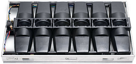
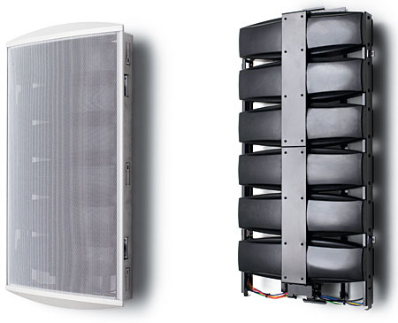
This could be a solution to the subwoofer problem and WAF issues..
Some of the text is in Danish, but I would think the principle and thoughts behind will be obvious for all. Or use Google translate ;-)
Hifiakademiet
One of my Hi-Fi friends (with Vifa arrays) has made one and says it works VERY good.
Some of the text is in Danish, but I would think the principle and thoughts behind will be obvious for all. Or use Google translate ;-)
Hifiakademiet
One of my Hi-Fi friends (with Vifa arrays) has made one and says it works VERY good.
That's almost like an air pump 🙂. I like how they can play up high in frequency and their low cone weight.
I'm kind of set on trying my conventional subs with the current woofers I have first (they don't need to play up that high) but will keep this in mind!
For 3 weeks now I wanted to start re-doing some post EQ but got side tracked into just listening to music...
I got some ideas when following the (mostly theoretical) line source thread that I wanted to try. I still want to but can't get past listening just yet... 😀
I know that problem.😛That's almost like an air pump 🙂. I like how they can play up high in frequency and their low cone weight.
I'm kind of set on trying my conventional subs with the current woofers I have first (they don't need to play up that high) but will keep this in mind!
For 3 weeks now I wanted to start re-doing some post EQ but got side tracked into just listening to music...
I got some ideas when following the (mostly theoretical) line source thread that I wanted to try. I still want to but can't get past listening just yet... 😀
Takes far too long time to listen to music 😛😉😀
I have found 'some' time over the last weekend to do part of what I was planning to do. Not nearly enough to do everything I wanted to try, but I'll get there in time...
At least I was able to do some cute experiments. I wanted to get a better grip on how to adjust tonality, including the mid/side EQ. It is obvious I can't use the 5 to 6 cycle window to determine tonal balance. The complete tonal balance is summed over a longer period than that. However that 5 to 6 cycle window more or less works best for me in EQ. Technically I use an ever changing window, as I keep in mind the particulars of the array. So at the top end I've always used a longer window, while at mid frequencies it drops under 5 cycles.
Let's see a time table:
The time in ms isn't exact, I used these values for some post EQ while keeping an eye on the waterfall plots. However tonality needed something longer. Based on where my ambience channels come in (delayed compared to mains) I figured a 20 cycle window (smoothed 1/3 octave) might be a pretty close representative for overall tonal balance (broad stroke) EQ.
I tried a few alternatives but liked this one best. Just finished another listening session with big grins and overall I'm pretty pleased. A few tweaks to the mid/side EQ, after all, good balance is everything.
The next days/weeks will tell me if it really works, nothing I do is ever based on a single listening session, I need way more time to convince myself.
More listening to do, oh boy, such a punishment 😀.
Edit: the above table is only for frequency correction. The phase correction window is much shorter and stops between 500-1000 Hz.
At least I was able to do some cute experiments. I wanted to get a better grip on how to adjust tonality, including the mid/side EQ. It is obvious I can't use the 5 to 6 cycle window to determine tonal balance. The complete tonal balance is summed over a longer period than that. However that 5 to 6 cycle window more or less works best for me in EQ. Technically I use an ever changing window, as I keep in mind the particulars of the array. So at the top end I've always used a longer window, while at mid frequencies it drops under 5 cycles.
Let's see a time table:
Code:
R - Band:   0,    20.0 Hz, width:  13230, FIR, 300,00 ms
R - Band:   1,    25.2 Hz, width:   9821, FIR, 224,48 ms
R - Band:   2,    31.8 Hz, width:   7416, FIR, 167.11 ms
R - Band:   3,    40.0 Hz, width:   5669, FIR, 128,55 ms
R - Band:   4,    50.4 Hz, width:   4373, FIR, 99,95 ms
R - Band:   5,    63.5 Hz, width:   3397, FIR, 76,43 ms
R - Band:   6,    80.0 Hz, width:   2652, FIR, 60,14 ms
R - Band:   7,   100.8 Hz, width:   2080, FIR, 47,07 ms
R - Band:   8,   127.1 Hz, width:   1636, FIR, 37,13 ms
R - Band:   9,   160.1 Hz, width:   1291, FIR, 29,29 ms
R - Band:  10,   201.7 Hz, width:   1021, FIR, 23,12 ms
R - Band:  11,   254.0 Hz, width:    810, FIR, 18,37 ms
R - Band:  12,   320.3 Hz, width:    643, FIR, 14,59 ms
R - Band:  13,   403.6 Hz, width:    512, FIR, 11,60 ms
R - Band:  14,   508.1 Hz, width:    409, FIR, 9,28 ms
R - Band:  15,   640.8 Hz, width:    327, FIR, 7,41 ms
R - Band:  16,   808.8 Hz, width:    262, FIR, 5,94 ms
R - Band:  17,  1019.2 Hz, width:    211, FIR, 4,79 ms
R - Band:  18,  1281.1 Hz, width:    171, FIR, 3,88 ms
R - Band:  19,  1613.4 Hz, width:    139, FIR, 3,15 ms
R - Band:  20,  2045.0 Hz, width:    113, FIR, 2,56 ms
R - Band:  21,  2575.7 Hz, width:     93, FIR, 2,11 ms
R - Band:  22,  3251.2 Hz, width:     77, FIR, 1,75 ms
R - Band:  23,  4132.5 Hz, width:     64, FIR, 1,45 ms
R - Band:  24,  5222.0 Hz, width:     54, FIR, 1,22 ms
R - Band:  25,  6618.6 Hz, width:     46, FIR, 1,04 ms
R - Band:  26,  8279.7 Hz, width:     40, FIR, 0,91 ms
R - Band:  27, 10470.8 Hz, width:     35, FIR, 0,79 ms
R - Band:  28, 13283.5 Hz, width:     31, FIR, 0,70 ms
R - Band:  29, 16635.5 Hz, width:     28, FIR, 0,63 ms
F - Band:  30, 20000.0 Hz, width:     26, FIR, 0.58 ms
The time in ms isn't exact, I used these values for some post EQ while keeping an eye on the waterfall plots. However tonality needed something longer. Based on where my ambience channels come in (delayed compared to mains) I figured a 20 cycle window (smoothed 1/3 octave) might be a pretty close representative for overall tonal balance (broad stroke) EQ.
I tried a few alternatives but liked this one best. Just finished another listening session with big grins and overall I'm pretty pleased. A few tweaks to the mid/side EQ, after all, good balance is everything.
The next days/weeks will tell me if it really works, nothing I do is ever based on a single listening session, I need way more time to convince myself.
More listening to do, oh boy, such a punishment 😀.
Edit: the above table is only for frequency correction. The phase correction window is much shorter and stops between 500-1000 Hz.
Last edited:
...More listening to do, oh boy, such a punishment 😀...
Enjoy and thanks sharing 🙂.
Can you try out these four general system EQ corrections and give feedback how it sounds ?
Shelving high:
23kHz Q0,5 +3,34dB
28kHz Q0,91 +12dB
25kHz Q0,55 +15dB
PEQ:
16725Hz Q3,0 -0,09dB
Gain structure:
There isn't much spl into recordings up there so maybe zero correction or -5dB or something ?
Know you have 25 times 68mm diameter tweeters a side and i have only one, relation is simmed theoretical off axis -12º point fall off for a 68mm diameter tweeter and oh boy this filter sounds fantastic on mine setup.
Visual it looks like this with a -5dB gain setting and know it looks hot but above audio band recorded material is not much.
Attachments

That does look kinda hot! 😱
Are you sure you're not compensating for 'our older, ageing ears'?
Let's be honest, we're not that young anymore... 😉
I don't think this could work particularly well for the arrays. It's pretty smooth up till 18 kHz, but I doubt I can get much more out of them. The 10F does better up top, as a single driver...
I've always wanted to experiment with ambient tweeters on top (AMT or ribbon), one day I may get around to that, it would mean more amps yet again, does it ever end?
- Home
- Loudspeakers
- Full Range
- The making of: The Two Towers (a 25 driver Full Range line array)