I should also mention the open-back box filled with Bonded Logic is surprisingly much less prone to internal standing-waves than an equivalent box with a solid back. If I recall right, Gary actually put a microphone in the box and measured what's going on, and opening the back nearly dropped the box modes to zero. (Remove the filling, though, and the improvement is considerably less, and a lot more sound zips out the rear.)
Since the back looks like an open window to the internal standing waves (unlike a hard, almost perfectly reflective surface), and the box is filled with a highly lossy material, the modes are de-Q'ed and store less energy. Subjectively ... well, it doesn't have as much box sound (you saw that coming, didn't you?). The enclosure walls are quieter, too, which is a nice benefit, and relaxes the requirements for internal cross-bracing (although still a good idea, you don't need as much).
I think of these as short transmission lines, aided by wideband high-loss filling. No deep bass, considering the size, but really good upper-bass and midrange.
I encourage the readers of this forum to try the internal microphone measurement for themselves, comparing:
1) Closed-back with no filling
2) Closed-back with Bonded Logic filling
3) Open-back with no filling
4) Open-back with Bonded Logic filling
Should be interesting.
Last edited:
Almost no effect at all. The ceiling tiles might quiet down vibration in the side or top panels, but they probably don't have enough mass to couple to the dense plywood or MDF of the enclosure walls. It takes a heavy material, like asphalt tile, to damp plywood or MDF enclosure walls.
The effect of ceiling tiles on internal standing-wave modes would be very slight, probably too small to measure. Acoustical ceiling tiles, to the extent they do anything at all, work from 500 Hz on up, and are most useful giving a moderate degree of isolation from the acoustical plenum where the air-conditioning ducts are in a typical office space.
Gary and I like Bonded Logic because it's the most broadband and effective acoustical absorber we know, far more pleasant to work with than awful fiberglass, and is not that expensive (if you buy it in bulk instead of Home Depot). The traditional long-fiber wool is good too, but it really has to be moth-proofed and is also prone to sagging. Wads of Bonded Logic, by contrast, are self-supporting, which is very convenient for filling enclosures.
Now if you wanted to be a little kinky with the ceiling tiles, you could try making the sidewalls from them, instead of using plywood or MDF. They'd be pretty lossy, which is a good thing in an open-back box. The open-back box will still need to filled with Bonded Logic, though, since that's what makes the open-back box work in the first place ... otherwise it's just a resonant old U-box, like an old-school TV or table radio.
If you want to get really weird, the sidewalls could be open-framed with one-by-twos, like a miniature house, with acoustical ceiling tiles glued on the inside and outside of the framing, and the space in between filled with (of course) Bonded Logic. Fill the interior of this little house with more Bonded Logic and leave the back open. Not exactly the most beautiful enclosure, but it would sound different.
Last edited:
Just when I thought it was safe to come out and make a little joke, something a lot weirder than this discussion comes out. Try this on for size: plants communicate with each other via sound. Here's the links:
BMC Ecology | Abstract | Love thy neighbour: facilitation through an alternative signalling modality in plants
and
http://www.biomedcentral.com/content/pdf/1472-6785-13-19.pdf
BMC Ecology | Abstract | Love thy neighbour: facilitation through an alternative signalling modality in plants
and
http://www.biomedcentral.com/content/pdf/1472-6785-13-19.pdf
Already got that going on in my garden. Got a book about it somewhere. You can even underplant cover crops to follow that will both shade the plants and give nice head start for next planting. THey sya that Basil helps both tomatoes and peppers, in growth, flavor, and pest control. I ahve a feeling some salty dogs have forgotten more about gardens than we will learn in the next couple years.
I encourage the readers of this forum to try the internal microphone measurement for themselves, comparing:
1) Closed-back with no filling
2) Closed-back with Bonded Logic filling
3) Open-back with no filling
4) Open-back with Bonded Logic filling
Should be interesting.
Also very important to note is the material density. The 3.5" R-13 cotton batts are about 2 pcf density; R-13 batts of fiberglass are generally around 1.5 pcf.
As is widely known, as stuffing is added to a box, effective box volume and damping increases while Fs decreases. As one would suspect, at some point any increase in density becomes a volume-robbing solid, and the Fs trend reverses. This turning point is typically somewhere around 1-1.5 pcf density (for a sealed box). Damping may sometimes continue to increase for a bit longer, but will also reverse as density increases.
For an open-back box, 2 pcf cotton might be nearly optimum for damping, but is also rigid enough function as moving mass (somewhat evidenced by the cotton "walkout").
Empirically, it's pretty easy to see what's going on with woofer-tester software, but it would be interesting to also correlate with mic measurements.
The most interesting possibilities lie in mixing densities. Whereas what we typically think of as stuffing only serves to de-tune a system, a layer of semi-rigid (like those fiberglass ceiling tiles, typically 3 or 6 pcf density) would enable resonance tuning, and bass extension like a passive radiator.
Noncoincident arrival time would certainly account for the mixture of blur and glare in commercial PA systems ... it's loud, all right, but you can't understand a word, thanks to a hash of non-coincident arrivals from the large arrays. Since the arrivals in the 0-3 mSec range are particularly critical for perception of intelligibility and tonal coloration, that's right where the line arrays will fall down, while still measuring fairly decent in the frequency domain.
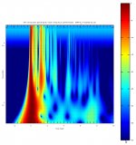
Made me think of migeO's work with wavelet analysis. What he provided gives a very clear picture of why even individual drivers can be confused sounding. The repeated patterns within the first 4ms are clearly shown. I suspect wavelet analysis could find and help in the elimination most horn difficulties too.
Bud
Attachments
Wavelets and the older engineer
Being lazy, can anyone recommend a primer or text book on wavelet analysis - I understand the concept but it post-dates my time at school.Made me think of migeO's work with wavelet analysis.
I was wondering about those array-design programs, and frankly, the rationale for line-array speakers in domestic audio. If the phase vectors are conveniently omitted from the calculations, no wonder the summation looks so pretty ... unlike real life, where phase addition/subtraction (at the listening position) matters a lot.
I jump into the time domain if summation looks questionable. That's what I think when I see a line array that's being promoted for domestic use in a high-end context. Yes, very pretty, but the arrival times for all these little drivers will be different, and worse, if the array is curved or electronically delayed to approximate curvature, what about distance compensation, eh?
Noncoincident arrival time would certainly account for the mixture of blur and glare in commercial PA systems ... it's loud, all right, but you can't understand a word, thanks to a hash of non-coincident arrivals from the large arrays. Since the arrivals in the 0-3 mSec range are particularly critical for perception of intelligibility and tonal coloration, that's right where the line arrays will fall down, while still measuring fairly decent in the frequency domain. The reader of the FR graph will not realize all those innocent-looking little ripples are the result of a large number of random-phase additions and subtractions from the noncoincident arrival times of the arrayed drivers.
Hello Lynn,
I'm one of the fools trying to build a line array for home use. I won't deny the troubles it gives but your post made me ponder. You talk about the arrivals in the 0-3 mSec being most important for perception of intelligibility.
Now take this example:

This is a picture showing the distance of the speakers to the listeners ear.
The difference in distance to the ear between the top most speaker and the center speaker is 191mm or 19.1 cm. That would create a window of 0.56 mSec of time smear. Well within the 0-3 mSec right?
I realise it will create comb filtering and interference between the separate sources but the timing differences don't seem that huge to me.
I do agree that bending the array backwards to simulate a point source would create bigger delays than this example.
Being lazy, can anyone recommend a primer or text book on wavelet analysis - I understand the concept but it post-dates my time at school.
It's the same as a CSD, except frequency and time axis have been reversed. And a sonogram style presentation is used.
Hi Lynn
I was thinking about the “chuffing fibers” issue you mentioned and it reminded me of some speakers I made for my living room once.
After a while, the pink FG started to exit via the port at the bottom and was noticeable on dark blue carpet.
My mom was not an audio person, but when I mentioned it she said (an an instant) “well put it in pillow cases liners for feather pillows”.
I reflexively scoffed (being “impossible” to find a solution that fast) but then I realized she actually had a good idea.
Those liners have a very fine weave fabric (I can’t ask her now but I think she called ticking) which contains the stuff and I ended up stapling them into the cabinet. Well, I wouldn’t have bothered if it was wool or cotton but the idea of FG floating around wasn’t appealing even in the 90’s.
Thoglette, this link would be a good place to start;
INDEX TO SERIES OF TUTORIALS TO WAVELET TRANSFORM BY ROBI POLIKAR
The idea is that since we are interested in a wide bandwidth, time is not the best ruler to measure with. It is why Group delay is not that useful, at 20Hz everything takes 1000 times longer than it does at 20,000Hz so “time” doesn’t show departures very well.
Wavelets and some other approaches say ok, let’s plot the departures based on how large they are compared to the wavelength or period of one cycle.
Viewed that way, a given thing (lets say a perfect 4th order decade wide band pass) has the same appearance at any frequency (like the impulse responses would be identical but different lengths in time proportional to the frequency). The same issue is present in the cumulative spectrum display; the proportional version is Cumulative Burst decay or STF which treats wavelengths or wave period as equal.
Fwiw, line sources are not dumb but like every “solution” it has tradeoffs and strengths. If loudspeakers were anything even remotely close to “perfect”, they would pass many generations in a generation loss recording, but they don’t, 3 or 4 passes is doing very very well.
The point is the are so many things wrong that there is no clear “best” solution. So many things wrong that when an early high resolution loudspeaker measurement was shown to a sharp electronic circuitry engineer, he said, huh, well whatever it is, it’s broken.
What can we hear? That is a valid question. We put wool or absorbent stuff around dome tweeters and mids, we try to avoid refractions in drivers surroundings and one can hear Higher order modes within a horn when you can hear with and without. All of these things considered to be adverse to sound quality are occurring in very short periods in time, <<3ms. People fret about response too 20KHz too but how large is that wavelength or quarter wavelength?
Intelligibility, the ability to understand random words (not sentences), this can only be measured by using a big list of words and large number of individual listeners. A legal indicator of intelligibility is the STIpa measurement which has proven to correlate to the measured data and is essentially language independent.
It works by using the Modulation Transfer Function measurement (google), the most familiar of these is the one used for optics. In the image below, line A is perfect on off modulation, line B is what limiting the MTF does and the black / while transitions show the loss of resolution that results.
http://photo.net/learn/optics/mtf/blur2.gif
The STIpa measurement uses 7 frequency bands (weighted to a speech spectrum) and performs a MTF measurement in each band.
Anything that “fills in” the off periods or inhibits the source form being on/off at that rate degrades the MTF.
Now, one might wonder is an optical style measurement of resolution applicable to musical audio?
I really think so but that answer to that like anything like single ended evaluation of a recording and musical, that is subjective.
So to me yes I think so but as far as an indicator / predictor of being able to hear/ understand random words, no doubt yes, that is proven.
Here is where reflected sound, reverberant sound and multiple arrivals, distortion and a myriad of other things all degrade the MTFs (and resolution I think).
For those with ARTA, it has an MTF measurement although little or no explanation how to read it. Each one is an a frequency band and shows an increasing rate of modulation and normally decreasing mtf reading.
AS one moves a mic away from the loudspeaker to the lp, one can see even then the MTF at the highest rates is degraded. Fwiw, I had attended an intelligibility seminar this spring and I asked the fellow who did research how high our hearing mtfs extended and he said they stopped around 30hz but only needed much lower rates for speech intelligibility.
The reason line arrays are normally curved or J shape is that a finite line array has very strong frequency dependent and position dependent behavior. That makes them an astigmatic point source instead of a cylindrical source. Don Keeles CBT sonar arrays take that farther and shade the amplitude away from center making them much more “constant” over a bandwidth.
In your case, you do have an opportunity to bypass most all the problems the commercial line arrays in live sound all face, you can extend yours floor to ceiling AND then you have thrown out ALL of those finite source length issues with a real (in the acoustic sense) line source, at least up to where your sources are ¼ wl apart.
Using your floor and ceiling as an acoustic mirror are the only ways possible to do that in the real world and yours already starts at the floor (making it acoustically twice as long already).
If you haven’t built yet, consider it, I have heard a couple true line sources made like this and they can be impressive and perform very well.
Best,
Tom
Thanks for that answer Tom. I am building them already and yes, they are floor to ceiling. But I chose to do it with full range drivers. Bypassing the need for crossovers but with DSP and because of the use of 3.5" drivers a bigger center to center spacing than I'd like to have.
I actually thought about using a line of paraline tweeters for the high frequencies until it became clear that it isn't easy to build those yourself as shown on this forum.
I actually thought about using a line of paraline tweeters for the high frequencies until it became clear that it isn't easy to build those yourself as shown on this forum.
Last edited:
In this case, you won't be able to avoid combing with any means of DSP as it will start fairly early....in fact too early to be remedied. Even my test array of 16 2" fullrangers had combing that was so objectionable, I scrapped the project. That's not to say line sources by nature are bad.....in fact when done right they're IMO one of the greatest listening experiences.....but alas....expensive when done as two ways.
 Gents. Please refrain from using the QUOTE button unless you really need it.
I do agree that bending the array backwards to simulate a point source would create bigger delays than this example.
Perhaps. But at the moment you are setting yourself up for an incredibly narrow (vertically) sweet spot. And weird side lobes (reflected off floor and ceiling) as Tom D. pointed out. Go look at phased array antennae design.
At least with zero delay (and short interdriver distances) you emulate a distant point source - and possibly reduce ceiling/floor reflections.
Multiple driver arrays are a form of "digitising" (in space) and the usual maths applies.
And reducing interdriver distances to suit 20kHz (-3db) point leads ulitimately to long ribbon drivers (eg. ambience) which do work rather well, in my experience.
Last edited:
Not exactly, CSD reduces the window by sifting the start, wavelets creates a specific window range and shifts the constant sized window from start to end.It's the same as a CSD, except frequency and time axis have been reversed. And a sonogram style presentation is used.
Not exactly, CSD reduces the window by sifting the start, wavelets creates a specific window range and shifts the constant sized window from start to end.
You are right. Can we say similar to burst decay?
- Home
- Loudspeakers
- Multi-Way
- Beyond the Ariel