I think that the Karlson is one of the better designs for 'throwing' a bass/mid-bass punch in a larger outdoor area. Getting one to work at 40 Hz will require a design from the ground up.
Well, if you mean by 'throw', it has a wider pattern than a normal speaker of the same width/driver size, then yes, but 'throw' normally refers to a speaker's directivity over axial distance, which unless someone has measurements to prove otherwise is at best, no better than a basic baffle speaker of the same height/width.
Right, for a wider BW it ideally needs more series resonant couplers. Using higher aspect ratio ones should work, but HF 'ripple' may be excessive with less driver protection down low same as a TH.
GM
Just found this thread. These look great. How about modeling for the following coax tannoy's I own? Thanks in advance!
Tannoy 2046 8" Dual Concentric:
Znom: 8.000ohms
Revc: 4.400ohms
Sd: 196 cm^2
BL: 7.5253
Vas: 34.7
Cms: 635.4423 um/N
Mms: 23.2575g
Mmd: 21.6785g
Fi: 40.062Hz
Fo: 41.400Hz
Qms: 10.550
Qes: 0.470
Qts: 0.450
Pmax: 100W
Hvc: 10mm
Hag: 5mm
Xmax: 2.5mm
Cmx: 2.5mm
Cmo: 1mm
No: 0.51%
SPLo: 89.08dB
SPL 2.83V/m: 91.10
Just found this thread. These look great. How about modeling for the following coax tannoy's I own? Thanks in advance!
Tannoy 2046 8" Dual Concentric:
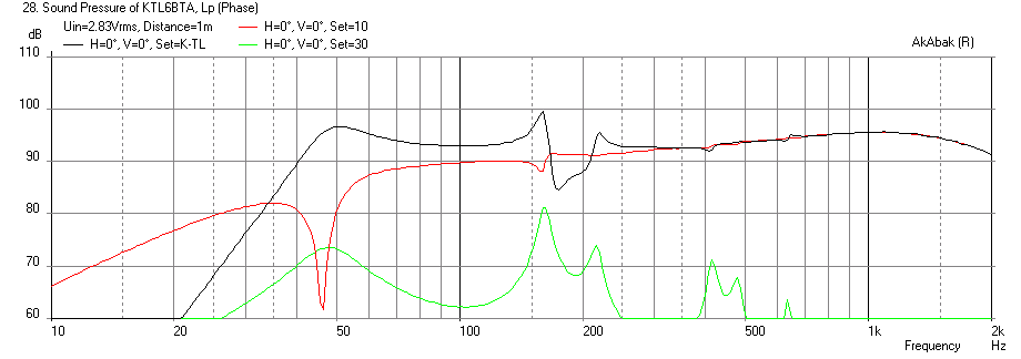
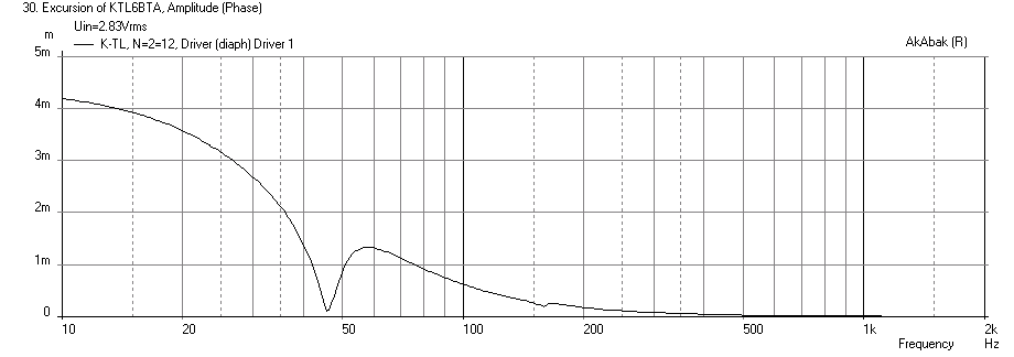
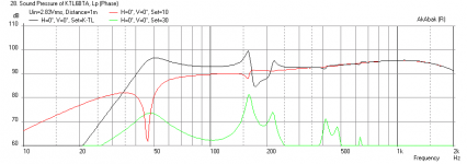
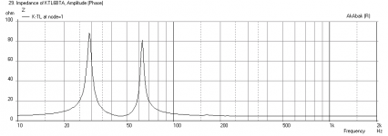
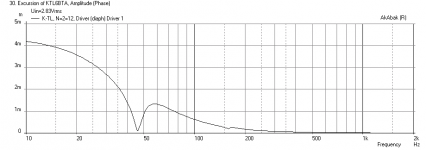
Here is the simulation with walls really far away. The Tannoy looks pretty good - you need to scale the width and depth by 0.67X - leave the height alone.
SPL vs Freq
Impedance

Cone Excursion
Attachments
Kind of related to this is the RCA Fan K-slot loaded BLH speaker. I just modeled it in Akabak and posted in this thread:
http://www.diyaudio.com/forums/full-range/238794-fe168e-fe208e-sigma-project-ideas-6.html#post3635567
http://www.diyaudio.com/forums/full-range/238794-fe168e-fe208e-sigma-project-ideas-6.html#post3635567
Here is the simulation with walls really far away. The Tannoy looks pretty good - you need to scale the width and depth by 0.67X - leave the height alone.
This is scaling the "original" Karsonator, NOT the Karsonator-8, correct?
This is scaling the "original" Karsonator, NOT the Karsonator-8, correct?
Yes, original (29.5 in tall x 15.25 in wide).
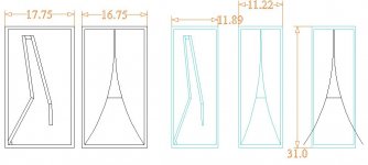
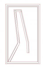
Question on scaling...the two left in black are original size. The two directly to the right in blue are scaled .67 in width and depth. Obviously, I have to do some work to get the plywood thicknesses in line.
However, does the K-slot also change shape, or should it be truncated as in the second shrink example with the black lines showing its original shape?
PS, thanks to tb46 for the .pdf. It opened directly in CAD without having to redraw it.
However, does the K-slot also change shape, or should it be truncated as in the second shrink example with the black lines showing its original shape?
PS, thanks to tb46 for the .pdf. It opened directly in CAD without having to redraw it.
Attachments
Last edited:
Hi tomlang,
I'm just trying to learn a bit about the Karlson enclosures myself. But, I assume that the slot should be scaled too (your blue line drawing). From what I've been able to gather there is a lot of room for experimentation.
Good that someone is getting use out of this drawing, I was hoping to fit this project into my "spare time", but right now, there is very little of that.")
Regards,
I'm just trying to learn a bit about the Karlson enclosures myself. But, I assume that the slot should be scaled too (your blue line drawing). From what I've been able to gather there is a lot of room for experimentation.
Good that someone is getting use out of this drawing, I was hoping to fit this project into my "spare time", but right now, there is very little of that.
Regards,
xrk, based on your sims, should I go ahead with the ".67" wxd scale build or do you think some other scale factor would make much difference? Do you have the transient response graph for the Tannoy driver?
Also, what about stuffing these? Is there any used at all or "too taste"? I assume the sims are no stuffing?
Also, what about stuffing these? Is there any used at all or "too taste"? I assume the sims are no stuffing?
Tom Lang,
Go with the 0.67x scale (width and depth) 1.0x height for the Tannoys as that was the optimal scale I arrived at. The sims include stuffing from the closed end all the way down through the bottom turn, right before it goes up. Use moderate density of polyfill. You can adjust to taste by adding or removing through driver cutout. The stuffing from closed end to driver can be more dense. I will have to calc impulse response but it is the inverse Fourier transform of the freq response, and seeing how smooth that is, it should look good. Before you cut wood, let me double check sims one more time to make sure I have the scaling correctly applied.
Go with the 0.67x scale (width and depth) 1.0x height for the Tannoys as that was the optimal scale I arrived at. The sims include stuffing from the closed end all the way down through the bottom turn, right before it goes up. Use moderate density of polyfill. You can adjust to taste by adding or removing through driver cutout. The stuffing from closed end to driver can be more dense. I will have to calc impulse response but it is the inverse Fourier transform of the freq response, and seeing how smooth that is, it should look good. Before you cut wood, let me double check sims one more time to make sure I have the scaling correctly applied.
Last edited:
Tom Lang,
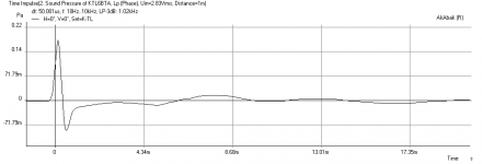
Here is the impulse response with the Tannoy 2046 - looks pretty good. The drawings should be scaled 0.67X in WIDTH ONLY. I mistakenly thought the depth was scaled too but it should be left the same (deep box) - sorry about that.
X
Here is the impulse response with the Tannoy 2046 - looks pretty good. The drawings should be scaled 0.67X in WIDTH ONLY. I mistakenly thought the depth was scaled too but it should be left the same (deep box) - sorry about that.
X
Attachments
TB46 and Tom Lang,
The drawings look good and yes, the K slot should be scaled like in the blue drawing. Experiment with the slot - it is easy to change.
Correction. The drawing should be scaled in Width only (so the side view should look like the black drawing on left), and the front view should look like the blue drawing on right.
Got it, thanks! So all the Tannoy plots above reflect .67 wide, 1.0x deep, and 1.0x height, correct?
YES.
Karlsonator 6 for FE167E
Prior to building the large enclosure for the Tannoys above, I will build the much smaller Karlsonator 6 for pair of FE167E that I have.
The FE167E is virtually identical to the FE164E which was built in a Karlsonator 6 below.
The Karlsonator Six (Page 1) / Karlson / Fullrangedriver Forum
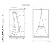
A question on the enclosure, however, it appears to show two builds, one with dotted red lines? Can anyone (Greg B?) elaborate?
Prior to building the large enclosure for the Tannoys above, I will build the much smaller Karlsonator 6 for pair of FE167E that I have.
The FE167E is virtually identical to the FE164E which was built in a Karlsonator 6 below.
The Karlsonator Six (Page 1) / Karlson / Fullrangedriver Forum
A question on the enclosure, however, it appears to show two builds, one with dotted red lines? Can anyone (Greg B?) elaborate?
Attachments
Karlsonator 6 for FE167E
Prior to building the large enclosure for the Tannoys above, I will build the much smaller Karlsonator 6 for pair of FE167E that I have.
The FE167E is virtually identical to the FE164E which was built in a Karlsonator 6 below.
The Karlsonator Six (Page 1) / Karlson / Fullrangedriver Forum
A question on the enclosure, however, it appears to show two builds, one with dotted red lines? Can anyone (Greg B?) elaborate?
The internal red-dotted panel is about equivalent to the two-piece one, if you want to build this way. The red Karlson-slot is only to show an alternative profile to experiment with. The black lines are arcs from a 39" radius as noted, but the red line appears not to be radial. I'd probably go with the black K-slot.
What material will you be using? I suppose one could get away with 0.5" BB-ply as per the plan, but 0.75" would really be ideal. Cool thing how lateral bracing is inherently good. Hardwood dowels to the back panel might be a good idea, as would be for the wings. ~1" internally from the K-slot on each side and roughly half-way up the front chamber. Front-mounting the driver and using the black-trace wing profile should remove the need for removable panels and make for a more inert/solid cabinet.
IG
Last edited:
Karlsonator 6 .5 vs. .75 inch thick material
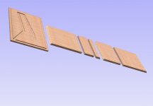
I'm going to use the Home Depot aracao plywood that is .73 inches thick. I took into account the extra thickness in the hard to read drawing shown.
I started to program the CNC. All panels will be rabbeted, mitered, and cut by the machine using a 1/4" straight bit as shown in the rendering of a few of the panels.
I'm not sure I will brace this since I am using 3/4" thick material.
Attachments
Nice, possibly the first CNC Karlson?
Bracing can always be added later if you feel it is needed. I was surprised at the pressure exerted on the wings of my K12 and bracing them really helped. I did not brace that of my smaller SK8, also built from 18mm BB-ply, but they could have used it as well.
Looking forward to see how this turns out!
IG
- Home
- Loudspeakers
- Full Range
- Karlsonator