I appreciate your full and clearly stated explanation. Sounds good to me that you see no arbitrarily chosen fudge factors sneaking into your model. Also good to understand that we stand together as experimentalist at heart.
So now we can get on with THE TEST: do the outputs of your model sufficiently resemble the empirical findings closely enough that we can all agree, "A Karlson acts pretty much like a waveguide (as legitimately modeled by a series of waveguides)"?
Ben
I don't have a K15 or Karlson (except the mini Karlsonator that I built) so I will leave the judgement to K15 owners and others on this forum with more experience using them, whether or not my model has predicted simulation results that resemble with empirical measurements enough to say that a Karlson can be modeled as a series of waveguides. But in general, aren't all (non open baffle) speakers in essence some sort of waveguide or another?
I am currently taking a crack at modeling an open baffle and it seems easy but I am still figuring it out and seeing that there may still be a small waveguide - in essence the driver cutout where the waveguide length is the short distance of the thickness of the material.
I might try to model a nice open baffle multi driver system like the Linkwitz Phoenix or Orion one of these days... I am really interested in the dipole push/pull woofer with one slot in the front and two slots in the back. Should be easy. The harder part will be to model the soft dome tweeter. I know AkaBak can do that, just have not gotten there yet.
The question is (once again): "what is a Karlson?"
They range from a 4th to 8th order band-pass [BP] alignment depending on model. No wave guides unless you can call a horn profile shaped terminus [vent] a wave guide, no TL action in the speaker's gain BW, it's just a collection of resonant cavities designed to focus the cab's gain over a relatively narrow BW.
GM
Thanks to xrk971 for the efforts to properly model this beast. The attempts to quantify it by combining known topologies was going on for years and never resulted in a useful predictive model.
And thanks to Freddi for continuing to carry such a strangely shaped flag.") .
.
For years I've been researching all manner of speaker designs with one eye looking towards building a hi-efficiency solar powered PA for small outdoor gatherings (60-100persons) and I'm curious if anyone thinks a Karlson that reaches from say 40hz to 500hz without sig dips might be a feasible design goal? As I understand it a TH just can't reach that high given the narrow bandwidth and QWL reliance.
I've run across plenty of CD horns that can handle from 500 on up, but I haven't seen a single hi-efficiency box that provides bass, midbass and lowmids with strong gain. Besides the desirable dispersion characteristics for mating to CD-tops the Karlson's mythological status of having a cannon like midbass kick (and this thread's own reports that the throw and FR in open space is holding up) suggests it would be very well suited to small outdoor PA use. I'd be inclined to build some test boxen if people thought the TH-alike effect and bandpass nature was able to be tuned to a wider range in the Karlson topology.
And thanks to Freddi for continuing to carry such a strangely shaped flag.
.For years I've been researching all manner of speaker designs with one eye looking towards building a hi-efficiency solar powered PA for small outdoor gatherings (60-100persons) and I'm curious if anyone thinks a Karlson that reaches from say 40hz to 500hz without sig dips might be a feasible design goal? As I understand it a TH just can't reach that high given the narrow bandwidth and QWL reliance.
I've run across plenty of CD horns that can handle from 500 on up, but I haven't seen a single hi-efficiency box that provides bass, midbass and lowmids with strong gain. Besides the desirable dispersion characteristics for mating to CD-tops the Karlson's mythological status of having a cannon like midbass kick (and this thread's own reports that the throw and FR in open space is holding up) suggests it would be very well suited to small outdoor PA use. I'd be inclined to build some test boxen if people thought the TH-alike effect and bandpass nature was able to be tuned to a wider range in the Karlson topology.
Let me see if I understand any of that. Funny thing, Paul Klipsch referred to the Karlson dismissively as a multi-resonant cabinet.They range from a 4th to 8th order band-pass [BP] alignment depending on model. No wave guides unless you can call a horn profile shaped terminus [vent] a wave guide, no TL action in the speaker's gain BW, it's just a collection of resonant cavities designed to focus the cab's gain over a relatively narrow BW.
GM
But let me take a closer look at this here modeling enterprise. We have a Karlson sitting in a room and the resulting frequency curve. Then we have guys (often very clever guys) making configuring parameters until they come upon a set of parameters and then they say, "Aha, this model of a 4th to 8th order...." and so on appears to resemble the acoustic measurement.
Granted, we expect the set of parameters to have some intuitive resemblance to the way a Karlson is built. But given the looseness of the test ("... appears to resemble..."), the range of options, and the cleverness of the guys.... Well, it is something like academic research where once in a while a "false" conclusion will be reached from research by statistical fluke.
Am I wrong?
Ben
Maybe this discussion should be going on in the Karlson thread proper, this is the Karlsonator which is clearly a folded TL with a Karlson aperture on the terminus. The approach I used to model the aperture is based on a series of variable area vent hole radiators which have the vent area match the equivalent area of a real K aperture. I have not seen why this approach is inherently wrong - in fact using the calculus of infinitesimal parts will yield the exact answer. The question is how small dovyou have the make the steps. This was examined and convergence was seen at 9 steps. Probably has to do with requirement that steps are << than wavelength of interest. The Karlson "Ultra Fidelity" enclosure or the K15 on the other hand is a series of connected chambers or waveguides that are actually quite straight forward to model. As I said, I use no adjustment "knobs", only the physical dimensions of the design as inputs to define the chambers or transmission line segments.
with a good coax or woofer plus stuff, the Karlson, although not going as low as the Klipschorn, probably sounded more accurate and natural overall depending upon room and placement. I've had cornerhorns from 40 years ago til now and still have K-horns. There is nothing wrong with the original Karlson and it will play well outdoors.
a discussion of K15's front and rear shelf function might be interesting.
a discussion of K15's front and rear shelf function might be interesting.
Last edited:
Let me see if I understand any of that. Funny thing, Paul Klipsch referred to the Karlson dismissively as a multi-resonant cabinet.
And he is correct, which describes a 'textbook' 4th - up BP, so not sure what the rest of your post is about WRT Karlsons unless you're referring to all the various 1/4 and 1/2 WL [ML]TLs that merely have Karlson 'coupler' vent openings and sometimes similar responses, such as the Karlsonator, so shouldn't be lumped in with the original Karlsons and its legitimate clones, adaptations to my way of thinking.
GM
Last edited:
a discussion of K15's front and rear shelf function might be interesting.
The shelve's function is to create a vent between chambers and why there's no TL action in the cab's gain BW as Karlson implied simply because the various chamber's aspect ratios aren't high enough.
GM
They range from a 4th to 8th order band-pass [BP] alignment depending on model. No wave guides unless you can call a horn profile shaped terminus [vent] a wave guide, no TL action in the speaker's gain BW, it's just a collection of resonant cavities designed to focus the cab's gain over a relatively narrow BW.
GM
I think that a waveguide is the most general description of any hard-walled enclosure that contains sound. Whether it is a sealed box, a bass reflex, a transmission line, or a horn, they are all waveguides as they support a wave inside with boundaries defined by the rigid wall. I also use the term because the primitive element that I use to model a speaker in AkAbak is the 'waveguide' consisting of an inlet cross sectional area, an outlet cross sectional area, a length, and a profile (linear, conical, exponential). Even though there is an inlet or outlet, it can be a sealed wall, and in fact I use a three waveguides to model a standard bass reflex and it works. The first is from the top to the driver center, the second is from the driver to the vent, and the third is from the vent to the bottom. The vent could be modeled as a waveguide but I use a 'duct' element as it has built in round cross sectional areas already. With this type of bass reflex model, depending on the length of the 'waveguide', the bass reflex can transition to a MLTL - same model just different lengths on the waveguide elements.
Anyhow, that is why I refer to the Karlson model as having interconnected waveguides.
Thanks to xrk971 for the efforts to properly model this beast. The attempts to quantify it by combining known topologies was going on for years and never resulted in a useful predictive model.
And thanks to Freddi for continuing to carry such a strangely shaped flag.
For years I've been researching all manner of speaker designs with one eye looking towards building a hi-efficiency solar powered PA for small outdoor gatherings (60-100persons) and I'm curious if anyone thinks a Karlson that reaches from say 40hz to 500hz without sig dips might be a feasible design goal? As I understand it a TH just can't reach that high given the narrow bandwidth and QWL reliance.
I've run across plenty of CD horns that can handle from 500 on up, but I haven't seen a single hi-efficiency box that provides bass, midbass and lowmids with strong gain. Besides the desirable dispersion characteristics for mating to CD-tops the Karlson's mythological status of having a cannon like midbass kick (and this thread's own reports that the throw and FR in open space is holding up) suggests it would be very well suited to small outdoor PA use. I'd be inclined to build some test boxen if people thought the TH-alike effect and bandpass nature was able to be tuned to a wider range in the Karlson topology.
Anthony Bisset,
Thanks for the acknowledgement.
I think that the Karlson is one of the better designs for 'throwing' a bass/mid-bass punch in a larger outdoor area. Getting one to work at 40 Hz will require a design from the ground up. Regards,
X
below is a one-sheet and certainly not optimal K-coupler loaded with a cheap Eminence 18 vs a Yorkville horn - - the big dip would not have been if it had either a K15 vent or different front chamber proportions - - the commercial horn had a lot more distortion
50Hz 20vrms - horn had 20dB more H2
34Hz sine
50Hz 20vrms - horn had 20dB more H2
An externally hosted image should be here but it was not working when we last tested it.
34Hz sine
An externally hosted image should be here but it was not working when we last tested it.
Last edited:
@ xrk971
I have a pair of unused kef's B139b, can you be so kind and run sim for them?
fs - 25 Hz
Sd - 349 cm^2
Re - 7.2 Ohm
Le - 0.97 mH
mms - 54 g
xmax - 7 mm
Qms - 6
Qes - 0.39
Qts - 0.37
Vas - 127 l
Bl - 12.5
Thnx
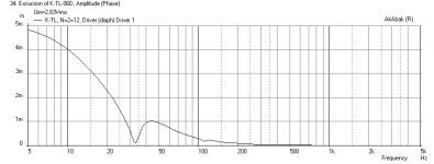
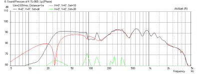
Here is a sim of the KEF with a stock Karlsonator in plot 1 - it has a very high bass peak that may cause "boominess". Second plot is the Karlsonator scaled by 18/15 in height and depth and by 10/12 in width followed by 1.5x in the upper vent cross sectional gap - seems to be flatter and tuning freq is about 33 Hz. The third plot is the impedance with the modified cabinet, the fourth plot is the cone excursion with the modified cabinet. All sims were with speaker placed with back 12 in from wall and 2.83v input measured at 1 m.
Attachments
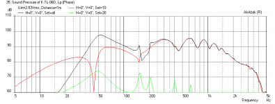
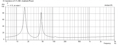
Here is a sim of the KEF with a stock Karlsonator in plot 1 - it has a very high bass peak that may cause "boominess". Second plot is the Karlsonator scaled by 18/15 in height and depth and by 10/12 in width followed by 1.5x in the upper vent cross sectional gap - seems to be flatter and tuning freq is about 33 Hz.
Thank you, you are fast
Second graph looks better but still is not flat enough, I would say. Especially at cut off region.
I don't understand your scaling system. What does mean "18/15 in height and depth"? I understand scaling factors like 1:2, or 1:25, or 2:1.5, or similar. Would you like to explain?
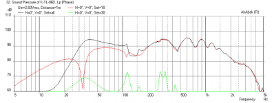
Thinking about why the KEF driver is behaving the way it does, I decided to try really changing the fs of the cabinet in a big way to get it to be closer to the driver fs which is very low. So I made the vertical and depth scale of 1.9X and the width scaled by 0.75X, and after the above scales are applied, scale the vent height by 2.3X - you get a flat response. I also added a 3 ohm + 1.2 mH coil in parallel as a BSC to tame the high end to balance it with the bass. The dip at 120 Hz is room placement dependent. Hope this looks better but it says you will have a very large speaker nearly 5 ft tall! 30 Hz to 100 Hz bass shelf is not bad - this speaker can sound really nice - you will need a tweeter crossed at say 1.25 kHz to make it whole though. Is this something worth trying or is the cabinet too big?
Attachments
Last edited:
Thinking about why the KEF driver is behaving the way it does, I decided to try really changing the fs of the cabinet in a big way to get it to be closer to the driver fs which is very low. So I made the vertical and depth scale of 1.9X and the width scaled by 0.75X, and after the above scales are applied, scale the vent height by 2.3X - you get a flat response. I also added a 3 ohm + 1.2 mH coil in parallel as a BSC to tame the high end to balance it with the bass. The dip at 120 Hz is room placement dependent. Hope this looks better but it says you will have a very large speaker nearly 5 ft tall! 30 Hz to 100 Hz bass shelf is not bad - this speaker can sound really nice - you will need a tweeter crossed at say 1.25 kHz to make it whole though. Is this something worth trying or is the cabinet too big?
thank you for explanation, now it's clear
this new sim looks nice but 5 ft tall box is probihitive. I would go up to 1m, maybe 1.2 m if cabinet is not too wide. driver is 21 cm x 30 cm so if box could accommodate driver in portrait orientation that would be perfect.
on top of kef I would like to place Fountek FE85 and cross it @ 300Hz or so.
bass does not need to be 30 Hz deep, f3 around 38 Hz would be very nice, even 40 Hz is ok, but the curve should be as flat as possible, something like your last sim. that is one nice looking fr plot
if you can cook something like that I would be very happy and build it.
........they are all waveguides as they support a wave inside with boundaries defined by the rigid wall.
Anyhow, that is why I refer to the Karlson model as having interconnected waveguides.
Not in any audio related documents I’ve read, only for ones with a high enough aspect ratio to actually be one in the speaker’s gain BW. The rest are assumed to have a ~uniform particle density and why speaker design programs assume the contained air mass is a one piece ‘solid’ to keep the calculations relatively simple, ergo can't sim any type of [ML]TL.
Again, none of the various original Karlson models have resonant chambers with a high enough aspect ratio to support a ‘wave’, ergo don’t qualify as waveguides.
GM
- Home
- Loudspeakers
- Full Range
- Karlsonator