of course, the nominal Re of that blue cone driver was the give-away would a 12pe32L with its low qts be too lean and bumpy in a similar bulk Karlsonator? http://www.parts-express.com/pdf/294-660.pdf
would a 12pe32L with its low qts be too lean and bumpy in a similar bulk Karlsonator? http://www.parts-express.com/pdf/294-660.pdf12PE32 sim
Freddi,
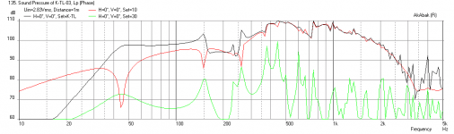
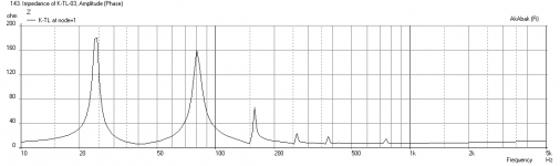
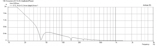
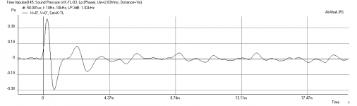
This is a very nice driver and it does quite well in a stock Karlsonator (first plot). Second plot is impedance, third is cone displacement (hardly moves), and last is impulse function. I think reducing Vb can improve response since the Qts is very low.
X
of course, the nominal Re of that blue cone driver was the give-away
Freddi,
This is a very nice driver and it does quite well in a stock Karlsonator (first plot). Second plot is impedance, third is cone displacement (hardly moves), and last is impulse function. I think reducing Vb can improve response since the Qts is very low.
X
Attachments
Get me some T/S params for your 5 in drivers and I will simulate and optimize a Karlsonator for you. A Karlsonator is a hybrid mass loaded tapered quarter wave transmission-line (ML-TQWT) with an Karlson-coupler on the output "horn".
Sorry, I can't do that. The speakers I'll use are recycled from trash and repaired by a friend whose work is just it: repair speakers, and uses what he find in the market.
I want a design for a generic speaker, I had done some calculus scaling down the original Karlson enclosure.
Do you have a way to measure the TS params? Without it, any design will be just guessing and hoping for something that sounds good. There is a way to measure using downloaded software and pc soundcard and a resistor. There is no such thing as a generic design (except maybe open baffle or sealed box with stuffing) especially with a Karlson that is scaled down. You can try a mini Karlsonator scaled to 0.5x scale and see how it works. If it is a very high Qts driver it may not work well. If it came from car audio, probably high Qts.
Sorry, I can't do that. .
Rod Elliot has a useful guide to measuing T/S parameters
A PC can be used to generate known frequencies - or use a test tone CD (I have Stryke's at home). Then you only need an A/C multimeter( and some resistors)
What is the Karlson or Karlsonator being modeled as?
Ben
It is modeled as a series of waveguides with cross sectional areas matching the K15, the K aperture is modeled ( and approximated) as a series of 9 ports with areas prescribed by the K aperture function and spatial locations on the front matching the K15. The effect of the K aperture was tested for convergence by increasing number of ports to 14 with no substantial difference. The effect of the K aperture on spatial directivity was tested by turning it on and off. The post describing the modeling approach is here http://www.diyaudio.com/forums/full-range/213594-karlson-10.html#x
The general shape of the freq response, the impedance curve, the directionality all seem to be confirmed with either owners' measurements or experience so far. I think I got pretty close to what a Karlson is with the current model. One of the biggest tells was the fact that the K15 exhibits very poor scalability below a factor of 12/15, consistent with observations.
The Karlsonator is modeled using the exact same technique with connected series of waveguides and port array for the K aperture. The difference being the waveguides form a folded tapered quarter wave transmission line that is mass loaded and exits into a Karlson coupler.
So in effect, the models are as close as you can get using 1 dimensional lumped nodes methodology. The next step in modeling would be to do a fully 3 dimensional model using the ABEC software.
Thanks for the explanation, some of whose sophistication is wasted on me, but doing my best to understand.
You are right to recognize the need to "defend" the model since the output of lots of models kind of look kind of like other models, kind of. Since this thread is heading into a discussion of models, maybe you could provide a bit more justification besides suggesting the model output feels about right to some owners.
Funny, all these years I've been quite sure that the "signature feature" of the Karlson, those curved wings, serve no core purpose besides decoration and maybe some useful bit of shaping and dispersion. Help me see the error of my thinking. Although that is my starting point, I am agnostic about the truth of your model; I honestly want to know if your wave-guide model is true or not.
Ben
Last edited:
Ben,
I am not defending my model, it is what it is - an approximation of a complex 3 dimensional acoustic system as a series of one-dimensional waveguides. There will of course, be shortcomings. From what I have been able to gather, I don't think there is another model out there of the K15 or any other Karlson-coupler based speaker. IG81 has gotten some good mileage with a tapped-horn model, but that is all I know of. When you say is the model 'true' or not, there can only be gray shades of truth as this is an approximation in 1-dimension. One very good test, IMO, is the electrical impedance curve of the drivers in the system. The coupling of the driver and the enclosure's acoustical waveguides will present the impedance curve with signature in the form of peaks, the shapes, and locations. Look at my post http://www.diyaudio.com/forums/full-range/237948-speaker-kicks-butt-large-spaces-28.html#post3581889 and compare with Freddi's measured impedance curves in the subsequent posts. Judge for yourself.
I am not defending my model, it is what it is - an approximation of a complex 3 dimensional acoustic system as a series of one-dimensional waveguides. There will of course, be shortcomings. From what I have been able to gather, I don't think there is another model out there of the K15 or any other Karlson-coupler based speaker. IG81 has gotten some good mileage with a tapped-horn model, but that is all I know of. When you say is the model 'true' or not, there can only be gray shades of truth as this is an approximation in 1-dimension. One very good test, IMO, is the electrical impedance curve of the drivers in the system. The coupling of the driver and the enclosure's acoustical waveguides will present the impedance curve with signature in the form of peaks, the shapes, and locations. Look at my post http://www.diyaudio.com/forums/full-range/237948-speaker-kicks-butt-large-spaces-28.html#post3581889 and compare with Freddi's measured impedance curves in the subsequent posts. Judge for yourself.
Funny, I thought a model was something more than creative drawing exercise where one person can make a better picture than another person.You are right to say drawings aren't in any way true or false, if that is what you really mean. BTW, it is a different matter to say, "I think this is a sound way to capture the Karlson's true principle(s)..."
I thought that a model which seemed to have all the predictions looking OK would help us understand the underlying acoustic principles inside a Karlson. That is more like evidence of truth.
So back to my question: how to model a Karlson.
Ben
I thought that a model which seemed to have all the predictions looking OK would help us understand the underlying acoustic principles inside a Karlson. That is more like evidence of truth.
So back to my question: how to model a Karlson.
Ben
Last edited:
Ben,
I am still not sure what you are getting at with the line of discussion regarding the term "model". By "model", I mean to approximate reality through a defensible and well-reasoned choices of physics-based governing equations. So take a speaker cabinet and its driver, the only reality is the actual system itself connected to amp and source, sitting in a real room and you listen to it or use mics to measure it. The reality is only then approxiamated by the physical governing equations that relate the electronics (Ohm's law, Ampere's law, Farady's law, rtc) to the generation of pressure waves which are governed by the Navier-Stokes equations of motion and the mass conservation law (which are all really re-stated fluid dynamic versions of Newton's second law F=ma). These laws and equations are still, all approximations or 'models' of the reality of the interaction of matter at the atomic level. We could go on... perhaps I digress?
Anyhow, getting to your question: how to model a Karlson? Lucky for me, some really talented people developed AkAbak which is a general purpose lumped-node network solver specifically designed for acoustical problems. The name AkAbak comes from Acoustic Abacus. AkAbak takes a lot of the physics and encapsulates it into easy to use package that lets me concentrate on the physical aspects of speaker design (dimensions, T/S parameters, Amperes, Volts, Ohms, Henry's, Farad's etc.) As I said before, post #94 in the Karlson thread (here:http://www.diyaudio.com/forums/full-range/213594-karlson-10.html#post3528706 ) gives the full details of how I model the Karlson.
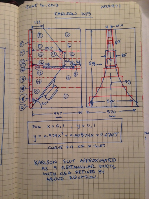
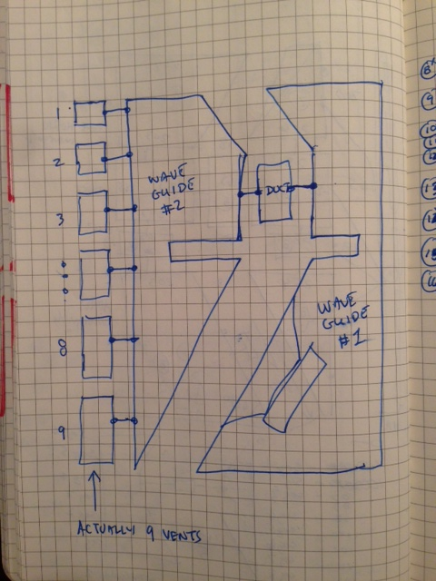
From the above sketch, you can see that I model it as a network of 26 waveguides/ducts. Each one is based on the dimension provided in plans of the K15. I model the Karlson aperture as a series of rectangular shaped ducts (vent ports) that transmit sound pressure from a waveguide to the outside world and allow it radiate out. The size of the series of vent ports is prescribed by a non-dimensional equation that is a curve-fit of the the Karlson aperture. When you add together the series of 9 vent ports, you see that you get a jagged looking Karlson aperture. When all this is put together as a system of 1-dimensional waveguides and you apply a simulated sinusoidal frequency sweep of electric current to the network, the resulting sound pressure is simulated at any desired distance/location away from the speaker.
Maybe you are asking how am I modeling the Karlson from the standpoint of is it a bass reflex coupled to aperiodic terminus horn? etc... Well, I don't really care, because that all is immaterial to the model which really is a series of interconnected ducts. The fact that there are several constrictions (at waveguide #3 and #12, for example) would probably make this a "Dual Chamber Reflex, Coupled to an Aperiodic-Boundary Tapped-Horn Coupler." So in a nutshell, maybe that is the "model" you are asking for?
I don't really know if the Karlson is a DCR operating with a coupled Tapped Horn - only a guess. But with AkAbak, and using a network of discrete waveguides - it really doesn't matter.
I hope this helps.
Regards,
X
I am still not sure what you are getting at with the line of discussion regarding the term "model". By "model", I mean to approximate reality through a defensible and well-reasoned choices of physics-based governing equations. So take a speaker cabinet and its driver, the only reality is the actual system itself connected to amp and source, sitting in a real room and you listen to it or use mics to measure it. The reality is only then approxiamated by the physical governing equations that relate the electronics (Ohm's law, Ampere's law, Farady's law, rtc) to the generation of pressure waves which are governed by the Navier-Stokes equations of motion and the mass conservation law (which are all really re-stated fluid dynamic versions of Newton's second law F=ma). These laws and equations are still, all approximations or 'models' of the reality of the interaction of matter at the atomic level. We could go on... perhaps I digress?
Anyhow, getting to your question: how to model a Karlson? Lucky for me, some really talented people developed AkAbak which is a general purpose lumped-node network solver specifically designed for acoustical problems. The name AkAbak comes from Acoustic Abacus. AkAbak takes a lot of the physics and encapsulates it into easy to use package that lets me concentrate on the physical aspects of speaker design (dimensions, T/S parameters, Amperes, Volts, Ohms, Henry's, Farad's etc.) As I said before, post #94 in the Karlson thread (here:http://www.diyaudio.com/forums/full-range/213594-karlson-10.html#post3528706 ) gives the full details of how I model the Karlson.
From the above sketch, you can see that I model it as a network of 26 waveguides/ducts. Each one is based on the dimension provided in plans of the K15. I model the Karlson aperture as a series of rectangular shaped ducts (vent ports) that transmit sound pressure from a waveguide to the outside world and allow it radiate out. The size of the series of vent ports is prescribed by a non-dimensional equation that is a curve-fit of the the Karlson aperture. When you add together the series of 9 vent ports, you see that you get a jagged looking Karlson aperture. When all this is put together as a system of 1-dimensional waveguides and you apply a simulated sinusoidal frequency sweep of electric current to the network, the resulting sound pressure is simulated at any desired distance/location away from the speaker.
Maybe you are asking how am I modeling the Karlson from the standpoint of is it a bass reflex coupled to aperiodic terminus horn? etc... Well, I don't really care, because that all is immaterial to the model which really is a series of interconnected ducts. The fact that there are several constrictions (at waveguide #3 and #12, for example) would probably make this a "Dual Chamber Reflex, Coupled to an Aperiodic-Boundary Tapped-Horn Coupler." So in a nutshell, maybe that is the "model" you are asking for?
I don't really know if the Karlson is a DCR operating with a coupled Tapped Horn - only a guess. But with AkAbak, and using a network of discrete waveguides - it really doesn't matter.
I hope this helps.
Regards,
X
I believe you have it backwards.
The question is (once again): "what is a Karlson?" Not, "what is a model?"
You begin by assuming the Karlson is a series of waveguides and you work with your model till you feel the model outputs you choose to look at resemble the way a Karlson measures when tested. That's what I mean by a "drawing" exercise. Fair enough as a first step. You draw a picture by adjusting the model.
By then we have see if we wish to make the inference that based on the rough similarity of your drawings and somebody's Karlson measurements, a Karlson really is a series of waveguides.
I can't say whether that is true or not and we all know that "similarity of pictures" are the best criteria we can hope for today. But, (1) since it is so easy to shape a model into reasonable shapes and (2) no one has offered any objective way to assess the goodness of the fit except for owners saying, "Gosh, the impedance curve has about the same number of bumps as my Karlson measures".... I think the question is still up in the air as to the underlying acoustic design(s) of the Karlson.
Ben
if the model gives some general directions and characteristics then its more than has been available til X's labor. The Karlson is a tough cookie
historically the Karlson has been trashed as BS, "frat bass", etc.
just got another BG20 straight out of the box WT3 says:
Re=6.564
fs = 42.39
qes = 0.4936
qms = 3.993
qts = 0.4393
Le = 0.03601 mH
historically the Karlson has been trashed as BS, "frat bass", etc.
just got another BG20 straight out of the box WT3 says:
Re=6.564
fs = 42.39
qes = 0.4936
qms = 3.993
qts = 0.4393
Le = 0.03601 mH
I believe you have it backwards.
The question is (once again): "what is a Karlson?" Not, "what is a model?"
You begin by assuming the Karlson is a series of waveguides and you work with your model till you feel the model outputs you choose to look at resemble the way a Karlson measures when tested. That's what I mean by a "drawing" exercise. Fair enough as a first step. You draw a picture by adjusting the model.
By then we have see if we wish to make the inference that based on the rough similarity of your drawings and somebody's Karlson measurements, a Karlson really is a series of waveguides.
I can't say whether that is true or not and we all know that "similarity of pictures" are the best criteria we can hope for today. But, (1) since it is so easy to shape a model into reasonable shapes and (2) no one has offered any objective way to assess the goodness of the fit except for owners saying, "Gosh, the impedance curve has about the same number of bumps as my Karlson measures".... I think the question is still up in the air as to the underlying acoustic design(s) of the Karlson.
Ben
OK, I see where you are going with this... I am an experimentalist by training and good with my hands, I build things and take data all the time. Back in th old days before pushing PowerPoint charts, I used to work with "modelers" who were often accused of putting "knobs" that they can "dial-in" any answer they want so it matches measurements.
How is this for you: there are NO "knobs" on my model other than the T/S parameters for the driver and the global scaling factor for the box size, and the vent size (which people adjust). So that when folks ask me how does such and such driver work in a 10/15 scale K15, I can quickly get an answer.
All dimensional parameters come from the published plans for the K15 - nothing more. My results are un-doctored and presented straight out of AkAbak.
If it is so easy, what model do you have that produces the right impedance and freq response?since it is so easy to shape a model into reasonable shapes
Last edited:
I appreciate your full and clearly stated explanation. Sounds good to me that you see no arbitrarily chosen fudge factors sneaking into your model. Also good to understand that we stand together as experimentalist at heart.
So now we can get on with THE TEST: do the outputs of your model sufficiently resemble the empirical findings closely enough that we can all agree, "A Karlson acts pretty much like a waveguide (as legitimately modeled by a series of waveguides)"?
Ben
So now we can get on with THE TEST: do the outputs of your model sufficiently resemble the empirical findings closely enough that we can all agree, "A Karlson acts pretty much like a waveguide (as legitimately modeled by a series of waveguides)"?
Ben
- Home
- Loudspeakers
- Full Range
- Karlsonator