Interesting. I know the memory distortion articles you have on your web page.
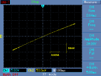
Another straightforward method to measure output impedance is an X-Y plot. X axis is a driving channel output voltage, it is injected as a current through 8 ohm resistor to the tested channel, and the tested channel output voltage is plotted on Y axis. It shows output impedance non-linearity quite well.
I will try to find some older measurements of more 'conventional' amplifiers.
In this example ratio of 50mv/10v x load =0.04ohms. Is this correct?
Perfect little oval represents phase angle. This would be do to propagation delay, and reactive elements in signal path through feedback network and amplifier stage(s) of DUT.
I assume input of DUT is tied to ground?
What about reference? How about bridge approach? Both amplifiers with same input signal, and identical loads connected at measurement point referenced to ground. And reference of measurement of driving amplifier with load to ground.
Voltage drop across output, no load v loaded ratio with purely resistive load seems most straight forward. Why isn't this a good approach?
In this example ratio of 50mv/10v x load =0.04ohms. Is this correct?
Perfect little oval represents phase angle. This would be do to propagation delay, and reactive elements in signal path through feedback network and amplifier stage(s) of DUT.
I assume input of DUT is tied to ground?
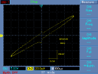
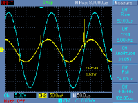
Well, X axis is the driving amplifier output. You may see 40Vp amplitude. This 40V injects through 8 ohm resistor current of 5A to the measured channel (40/8). 5A makes a 150mV voltage drop on Y axis. 150mV/5A = output impedance of measured channel is 0.03 ohms.
Ellipse reflects phase shift of the output impedance. This output impedance is like R + jwL. L is an inductance of wire from PCB to binding post at the rear panel + amplifier output inductance (this amp does not use an output coil). For 10kHz, you get 'broader' ellipse. For very low frequency, you get almost straight line, if the amplifier output impedance is not very non-linear.
Output load is referred to ground.
Well, X axis is the driving amplifier output. You may see 40Vp amplitude. This 40V injects through 8 ohm resistor current of 5A to the measured channel (40/8). 5A makes a 150mV voltage drop on Y axis. 150mV/5A = output impedance of measured channel is 0.03 ohms.
Another measurement, with low frequency, quasi-static. The resulting output impedance is again 0.03 ohms (0.075V/2.5A).
Attachments
Hello Mooly et all,
As I drop into this thread, I will first introduce myself. I have my degree of electronics at one of the best technical schools in Belgium. This was in the 70's, when we were still thought how tubes and transistors really worked. I have been interested in audio ever since and as it so happens, I have visited this site extensively over the last weeks as I am building a pre-amp just for the fun and to see what I can produce on an extremely low budget. And so I encountered this thread.
So far the intro. Now the question/remark...
I think I have to disagree with this. Firstly, why should you not be able to judge the sound with a very high quality headphone? My headphone reproduces FAR better quality than my speakers ever will. But what I miss in the headphone is the sound stage image, the 3D effect that you get when listening to speakers. BUT that image is not the definition of the soundquality of an amp rather is it a test of speakers and the room and the setup! So if I want to judge the sound quality of an amp, I actually prefer headphones, because it eliminates a bunch irrelevant information.
Secondly, the sound of a wire does not exist. Even wire (yes speakerwire) has a sound because it is sometimes measurably different and will therefore de facto be influential to the reproduced sound. If I can measure it, it makes a difference. Same goes for THD, TIM, capacitor linearity and type, slow transistors, and so on... So it is all a measure of approximation of that ideal wire. There are so-called specialists that dare to discuss with me the benefit of goldplated mains leads. If you believe that, then audio has become a religious battle.
The ideal wire in MY definition is the SETUP that makes me believe I am listening live to the performance of the musicians. THAT is what I strive for in my designs.
I basically tried to follow this thread and after page 6 or so I started wondering what this was leading up to. I mean: it is very normal and logical that two different amps will sound differently. This is common knowledge and numerous technical reasons exist to explain that. As a matter of fact, it is nearly impossible to have 2 amps sounding similar without both using the exact same design and components. So what are you trying to demonstrate, I ask myself? If the discussion is how to evaluate the sound or which is the better one, then I am affraid that there is no simple answer. For ME personally, I would say the best sounding amp/speaker/cable/whatever is the one that I MYSELF have decided is the best one according to MY taste and preferences.
And so my point is basically that you can test, measure, listen and evaluate the quality up to a point. You can prove technical deficiencies like a badly designed amp which sounds harsh or has a lot of transient modulation distortion or goes into limiting from the power supply or badly designed protection circuits. That is the easy selection, but when it comes to the listening-test then all of that becomes very subjective and personal taste and preference will decide what is best for YOU.
I think the only reasonable way to test audio equipment is to do a group test session and poll and ask the group how they liked it just by hands-up count or rating. Then you will get a group-averaged like or dislike. It would then be interesting to see if a correlation of reasons exists between the likes and also between the dislikes. That would tell you how the group experienced the device-under-test. And it probably will tell you which amp has the X-factor.
Regards, Luc
As I drop into this thread, I will first introduce myself. I have my degree of electronics at one of the best technical schools in Belgium. This was in the 70's, when we were still thought how tubes and transistors really worked. I have been interested in audio ever since and as it so happens, I have visited this site extensively over the last weeks as I am building a pre-amp just for the fun and to see what I can produce on an extremely low budget. And so I encountered this thread.
So far the intro. Now the question/remark...
How do you listen and evaluate such test? Answer... I don't know. Are headphones a realistic option ? I suspect not because when I replay these through headphones the effect or differences are obscured to a large extent and don't come across. On speakers then ? Well probably. The two files are chalk and cheese when auditioned this way. Maybe tests done this way could be more revealing of how close an amp comes to a piece of wire than all conventional testing.
I think I have to disagree with this. Firstly, why should you not be able to judge the sound with a very high quality headphone? My headphone reproduces FAR better quality than my speakers ever will. But what I miss in the headphone is the sound stage image, the 3D effect that you get when listening to speakers. BUT that image is not the definition of the soundquality of an amp rather is it a test of speakers and the room and the setup! So if I want to judge the sound quality of an amp, I actually prefer headphones, because it eliminates a bunch irrelevant information.
Secondly, the sound of a wire does not exist. Even wire (yes speakerwire) has a sound because it is sometimes measurably different and will therefore de facto be influential to the reproduced sound. If I can measure it, it makes a difference. Same goes for THD, TIM, capacitor linearity and type, slow transistors, and so on... So it is all a measure of approximation of that ideal wire. There are so-called specialists that dare to discuss with me the benefit of goldplated mains leads. If you believe that, then audio has become a religious battle.
The ideal wire in MY definition is the SETUP that makes me believe I am listening live to the performance of the musicians. THAT is what I strive for in my designs.
I basically tried to follow this thread and after page 6 or so I started wondering what this was leading up to. I mean: it is very normal and logical that two different amps will sound differently. This is common knowledge and numerous technical reasons exist to explain that. As a matter of fact, it is nearly impossible to have 2 amps sounding similar without both using the exact same design and components. So what are you trying to demonstrate, I ask myself? If the discussion is how to evaluate the sound or which is the better one, then I am affraid that there is no simple answer. For ME personally, I would say the best sounding amp/speaker/cable/whatever is the one that I MYSELF have decided is the best one according to MY taste and preferences.
And so my point is basically that you can test, measure, listen and evaluate the quality up to a point. You can prove technical deficiencies like a badly designed amp which sounds harsh or has a lot of transient modulation distortion or goes into limiting from the power supply or badly designed protection circuits. That is the easy selection, but when it comes to the listening-test then all of that becomes very subjective and personal taste and preference will decide what is best for YOU.
I think the only reasonable way to test audio equipment is to do a group test session and poll and ask the group how they liked it just by hands-up count or rating. Then you will get a group-averaged like or dislike. It would then be interesting to see if a correlation of reasons exists between the likes and also between the dislikes. That would tell you how the group experienced the device-under-test. And it probably will tell you which amp has the X-factor.
Regards, Luc
you can design amps that "sound different" - but you don't have to
if the intent of competent amp designers is accuracy - then all amps designed for technical accuracy should sound the same despite topology and devices - it is very easy now to get better than 60 dB matching over the audio frequency range into reasonable speakers
speakers with uneven impedance are easily dealt with with low, sub-milliOhm amp output Z over audio frequencies
PMA's recent posts have been a clear demonstration that amp output Z is measurable, can matter - and is controllable by design
if you want to compare amps with different output Z - just pad the lower Z (more accurate) one to match the "colored" amp - same for frequency response - just EQ
the Carver/Stereophile Challenge is the exemplar of this - Carver tweaking his $600 SS amp for a output null with Stereophile's own selection of "SOTA" tube amp and idiosyncratic speaker - Blind tested in their own listening room, their music
Stereophile's professional “golden eared” reviewers failed to distinguish them when listened to level matched, blind
Last edited:
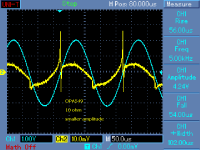
Some more mesurements on OPA549 output impedance. Current injected through 10 ohm resistor. Measurements show behavior of low biased output stage (probably quasi-complementary?) and low slew rate, at 1kHz and 5kHz. Cross-over behavior at low amplitudes is clearly demonstrated.
Attachments
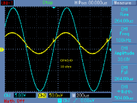
5kHz, in time domain. Such behavior leads to 'different' sound.
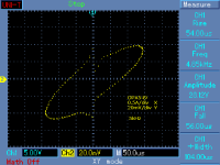
Edit: added measurement at smaller amplitude. For smaller amplitudes, nasty behavior dominates and output impedance is totally non-linear.
Edit: added measurement at smaller amplitude. For smaller amplitudes, nasty behavior dominates and output impedance is totally non-linear.
Attachments
Last edited:
Hi Pavel, nice measurements information, thank you.5kHz, in time domain. Such behavior leads to 'different' sound.
Edit: added measurement at smaller amplitude. For smaller amplitudes, nasty behavior dominates and output impedance is totally non-linear.
Regarding power amplifiers and loudspeakers, it is expected that by definition the reactive load exhibited by typical loudspeakers will return energy to the amplifier.
It is agreed that the damping characteristics of the amplifier will serve to quench this return energy, but as you demonstrate/measure this damping is typically a non perfectly linear function.
This non perfectly linear behaviour would help to explain perceived sonic differences according to loudspeaker cable type.
This non perfectly linear behaviour would also help to explain perceived sonic differences of loudspeakers according to amplifier type.
I agree that this level/frequency/load, damping behaviour is a fundamental behaviour to get 'right', and generally ignored, or dismissed, or wholly misunderstood.
IME simple standard Zobel compensation networks across the individual drivers rendering a loudspeaker flat overall impedance (including cable, excluding resonance bump) makes amplifier typical measured specs much less critical, in a sense....this is to be expected.
Dan.
Last edited:
Some more mesurements on OPA549 output impedance. Current injected through 10 ohm resistor. Measurements show behavior of low biased output stage (probably quasi-complementary?) and low slew rate, at 1kHz and 5kHz. Cross-over behavior at low amplitudes is clearly demonstrated.
Thank you Pavel for proving that components and their choice thereof matter a great deal. I could immediately see from the distortion trace that this opamp is having a badly designed asymetric output stage (difference in negative and positive slope!) and what you see is typical crossover distortion that you will always hear in the output. No amount of feedback will get rid of it. Even a perfect power output stage will be fed with this pre-distorted signal, so you basically amplify a small problem into a very big one. You can compensate by using feedback but the entire feedback loop behaviour will jump eratic near the crossover points to try and compensate this. Having a limited slewrate to make matters worse, this is an unusable opamp for any audio design and probably for ANY other application too.<br><br>
Dan, I would suggest you are right that the microfonic feedback will define sonic differences, but I would expect that to be dependent of the way the amplifier handles this return-signal. If the amp has not enough damping or this signal is managing to get into the amplifier feedback loop, then this return-signal will be amplified into the signal input chain by way of the feedback into the input differential amp. That definitly is going to affect sound as now an external feedback signal is mixed back into the original source signal. NOT good!
And you are on my line of thoughts when you say that this defines the type of amp because as I said before, a badly designed amp will exibit this behaviour if it is a class-B amp output. A class-A will not have this effect EXCEPT if the bad opamp that PAVEL has tested is used in the pre-stage because even a class-A output stage will simply amplify the distored output of the opamp.<br><br>
It cannot be better illustrated that quality of the component design is of prime importance and the tests of Pavel show how important it is that components should be tested and evaluated. The perfect op-amp is NOT perfect most of the times. It is probably also the reason why people prefer some opamp (like the opa2134) over another and why there is a limited number of sonically accepted reference op-amps like the OPA2134 or the venerable 5534.
<br><br>
The tests of Pavel have set the OPA549 on my blacklist. Thanks Pavel. Good info for me!<br><br>
Regards,
Luc
Yup, thats part of what we're sayin'......Dan, I would suggest you are right that the microfonic feedback will define sonic differences, but I would expect that to be dependent of the way the amplifier handles this return-signal. If the amp has not enough damping or this signal is managing to get into the amplifier feedback loop, then this return-signal will be amplified into the signal input chain by way of the feedback into the input differential amp. That definitly is going to affect sound as now an external feedback signal is mixed back into the original source signal. NOT good!
Regards,
Luc
Typical very cheap audio gear (portables etc) exhibits ringing because of the neg return pulse energy getting into NFB (not getting quenched sufficiently by the OPS), getting inverted and spat back out...decaying ringing/imd that is audible, and variable according to the load characteristics.
Because the effect is non linear wrt level/frequency/load, the level/distribution of the thd/imd distortion products keep moving !.
Happens with expensive amplifier/cable/speaker combos too.
In audiophile circles, this is referred to as 'sonic signature'.

Dan.
Last edited:
A class-A will not have this effect EXCEPT if the bad opamp that PAVEL has tested is used in the pre-stage because even a class-A output stage will simply amplify the distored output of the opamp.
Luc, we need to emphasize one fact here. The OPA549 is a power chip amplifier with output current up to 10A. Idle current is about 30mA only and output is most probably quasi-complementary. The bad behavior I have shown happens only if it is used as a power amplifier, with output stage deep in class B because of low load impedance. If it was used as a pre-stage, with negligible load, cross-over nastiness would not be present. But, then noise and low slew rate 9V/us of OPA549 should be taken into account. So, please let's not compare OPA2134 or NE5534 with OPA549, they are dedicated to very different amplifying purposes.
Hi Pavel,
Thanks for clarifying that.... I was about to write a question to you about your testing methods. I wondered if you had forgotten de micro before the A (so micro-amperes) not realising that you were testing a power opamp! I did not lookup the data about the opa549 at the time of my reaction. Carelessness that in a funny way bites me back... I stand corrected about that... I did not contemplate the use of poweramps so did not realise you were testing one of those. I do not use them myself. I only use the normal style opamps and discrete component power stages and that is reminiscent of the days when I had a Luxman C03 preamp and M03 poweramp. Today they would be considered dated (also the sound I guess) but at the time they cost a fortune and they were the best I ever got my hands on. They did great service for about 20 years!
Nevertheless, the op549 device is now on a double blacklist") on the poweramp-list and the avoid-list. As your tests have demonstrated, the device is not well conceived for audiophile use. I now looked at the datasheet and the bias-current drops even under 25 mA if the chip heats up over 75 deg C... So if you do a load test or use the device with too little cooling, then the test-result you have got is easily explained. But that is obvious to you of course... sorry.
on the poweramp-list and the avoid-list. As your tests have demonstrated, the device is not well conceived for audiophile use. I now looked at the datasheet and the bias-current drops even under 25 mA if the chip heats up over 75 deg C... So if you do a load test or use the device with too little cooling, then the test-result you have got is easily explained. But that is obvious to you of course... sorry.
My rant about components still holds then : measure before use! So I think it is great that you do this! And Dan is very much on the trace of why there is such a thing like sonic signature and what influences that. It certainly deserves further investigation. For me, I have a big aversion against big inductors in the speaker cross-over. I am researching the concept that their back-emf behaviour is the main culprit where it starts to act together with the cable and the speaker in a sort of resonant circuit. So I am now building several normal speakers and an active one to see where the differences are, if any of course.
I took a brief look at your site (time is tight this weekend) and I MUST say you build beautiful components! Looks great... I will have a further look this week...
Luc
Thanks for clarifying that.... I was about to write a question to you about your testing methods. I wondered if you had forgotten de micro before the A (so micro-amperes) not realising that you were testing a power opamp! I did not lookup the data about the opa549 at the time of my reaction. Carelessness that in a funny way bites me back... I stand corrected about that... I did not contemplate the use of poweramps so did not realise you were testing one of those. I do not use them myself. I only use the normal style opamps and discrete component power stages and that is reminiscent of the days when I had a Luxman C03 preamp and M03 poweramp. Today they would be considered dated (also the sound I guess) but at the time they cost a fortune and they were the best I ever got my hands on. They did great service for about 20 years!
Nevertheless, the op549 device is now on a double blacklist
on the poweramp-list and the avoid-list. As your tests have demonstrated, the device is not well conceived for audiophile use. I now looked at the datasheet and the bias-current drops even under 25 mA if the chip heats up over 75 deg C... So if you do a load test or use the device with too little cooling, then the test-result you have got is easily explained. But that is obvious to you of course... sorry.My rant about components still holds then : measure before use! So I think it is great that you do this! And Dan is very much on the trace of why there is such a thing like sonic signature and what influences that. It certainly deserves further investigation. For me, I have a big aversion against big inductors in the speaker cross-over. I am researching the concept that their back-emf behaviour is the main culprit where it starts to act together with the cable and the speaker in a sort of resonant circuit. So I am now building several normal speakers and an active one to see where the differences are, if any of course.
I took a brief look at your site (time is tight this weekend) and I MUST say you build beautiful components! Looks great... I will have a further look this week...
Luc
Yes, OPA549 is not a good part for audio. It has only 900kHz GBW so the distortion rises at higher frequencies even for a moderate load, where cross-over distortion does not dominate.
This thread is about power amplifiers possible sound differences. OPA549 is the power opamp and it was used as an example of the possible problems with output stages. You will also find measurements of a discrete, high power amplifier in this thread. I know it is boring, but individual posts do not make much sense if they are brought out of the context.
This thread is about power amplifiers possible sound differences. OPA549 is the power opamp and it was used as an example of the possible problems with output stages. You will also find measurements of a discrete, high power amplifier in this thread. I know it is boring, but individual posts do not make much sense if they are brought out of the context.
Why, thanks Luc...... And Dan is very much on the trace of why there is such a thing like sonic signature and what influences that. It certainly deserves further investigation.
Luc
I agree that big inductors can screw sounds.
Eons ago, I went to the trouble of Zobelling 8" woofer and 1" tweeter, rendering the cabinet flat impedance out to past 40kHz.
The woofer was connected full range and the tweeter bled in on 1.111uF or so IIRC.
The result was 3D imaging, fantastic extension in lows and highs, clarity, presence, and power handling, the amp ran cool and the building shook....clarity like ESL, AND power, and grunt, like proper PM/dynamic drivers.
Absolute polarity was perfectly revealed also.
It is to be expected that typical crossover networks will introduce phase rotations/aberrations that will obscure transient attack, reduce damping and confuse absolute polarity wrt frequency.
Amplifier load dependence/return energy behaviour is indeed a subject worthy of close investigation.
Kudos to Pavel for measuring that the typical damping factor spec as given is essentially meaningless.
Dan.
This thread has just been posted on Speakerplans as an interesting subject.
of course amplifiers have their own unique "Sound" as do devices used in the same Topology.
Bob Carver did all this many years ago with his study into "TFM" (Transfer Function Modification) in fact produced a range of Amplification as TFM.
he said he could replicate the "Sound Signature" of an Amp using it and went on to prove his point with Blind testing.
As the device issue I mentioned I get differing resultant "Sound" by using a different input pair from another. pretty much the same as a BJT amp will sound different from a MOSFET amp this also applies to different topologies of similar technologies as well as "Class" they may "Measure" the same figures but sound greatly different
- Status
- This old topic is closed. If you want to reopen this topic, contact a moderator using the "Report Post" button.
- Home
- General Interest
- Everything Else
- Listening Test... A Practical Demonstration That Amplifiers Have Their Own Sound.