Do you have a schematics of the amplifier under test, even a blind one or simplified?
It is a Technics amp that I got for 20€ at the pawh shop. Probably 20 years old, at least.
It sounds OK... I use it to drive the speakers on my desk.
A pet project of mine it to put it in a huge rack with a few bricks for the "feel" and have some audiophiles ABX it against some gold-plated gear

Schematics :
Technics SU-600 | Owners/Service Manuals, Schematics, Free Download, Reviews | HiFi Engine
EDIT : don't bother downloading this one
It is non-switching class AB, popular at this time (Technics calls this "New Class A"). It's a bunch of diodes in the output bases.
This does not solve Gm doubling at all, but at least there are no crossover glitches.
Last edited:
Interesting. I know the memory distortion articles you have on your web page.
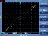
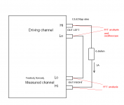
Another straightforward method to measure output impedance is an X-Y plot. X axis is a driving channel output voltage, it is injected as a current through 8 ohm resistor to the tested channel, and the tested channel output voltage is plotted on Y axis. It shows output impedance non-linearity quite well.
I will try to find some older measurements of more 'conventional' amplifiers.
Attachments
Last edited:
I will try to find some older measurements of more 'conventional' amplifiers.
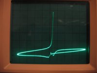
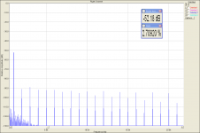
Got it. OPA549 power chipamp, measured at 10kHz, output impedance. I think especially Frank (fas42) would 'appreciate' sound of this amplifier
.This is class B crossover distortion in its full nastiness.
Attachments
Last edited:
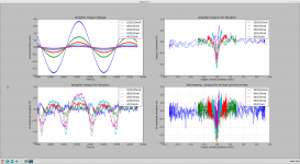
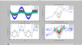
Here are more results.
In the first one, HF current is 200mA like before, and LF current is varied.
The global amplitude of gm variations does not change, but at low currents, the output does not heat, so the amp stays underbiased.
However, 200mA HF current is probably too much. The HF current used to measure output Gm should be less than the amplifier idle bias...
Second plot, HF current is much lower, 20mA, and LF current is varied.
Using a much smaller HF current allows it to stay fully inside the crossover region over a full HF period. This tells a lot more. Here, Gm variations are 10x more that previously, reaching 1%, which is actually a lot, considering this is after global feedback.
Gm versus current curve shows a deep "V" shape characteristic of underbiasing, Gm decreases as we approach the zero current point as the output transistors are current-starved. This is also visible in the bottom left curve.
Attachments
Reader Digest Version....ok, summary is the four transformer/bridge/cap supplies were individual in an outboard box and connected to the stereo amp 'mega ground module' by twisted pairs.Dan, interested in your experiments in creating a sizable local earth - this is something I've thought about, but haven't played with. What sizes of sheet are we talking about, and did you determine any relationships or optimum size for the material?
Thanks,
Copper (CGP) was 150 high x 100 wide, or so.
The four individual rails were 100 x 15 or so wide strips of thin flexible fibreglass pcb material and glued left to right on top of the ground plane (the rails spaced down the copper sheet).
The theory of the supply strips is that supply extra shunt caps and networks can be added at will, and pads can be isolated on the strips to enable easy insertion of series components.
Also that each of the thinly backed power strips constitutes an ideal capacitor in itself.
Also so that minimal loop areas can be implemented, and no crossings of conduction paths in CGP, NFB, or generally.
Power entered on the left of the strips, the 5 pin To-220 TDA2030's bridged the rails half way across, speaker wires exited to the left and returned to the ground plane between the associated rails half way over to the left, output zobel directly connected between amp output pin and CGP (component lead inserted into drill hole in CGP and soldered).
Signal entered from the right with shields directly soldered to right hand side of the CGP, and pos input pin grounded by resistor directly between pin and drill hole in CGP.
Ditto neg input pin CR bypass.
I hope you can visualise from my description
.This was an afternoon muck around to try proof of concept, lasted a week or so and then got canibalised.
Soldering to the CGP was one hell of a problem with the tools/equipment I had....that's why it got trashed....too hard to play with zobels or change any other components.
With the CGP some high weight copper clad pcb, and/or the right heating apparatus, this kinda idea ought to be sort of doable diy.
So the proof of concept was to see what an effectively infinite earth might do.....and the result was as predicted
.With everything so solidly earth tied to each other, mono accuracy, stereo placement, and sounds from far away front and far away rear just apparitioned.
Absolute polarity became mission critical.
Having an electrically ideal earthing scheme does one thing......I feel that this sheer mass of very old, hundreds of times annealed laundry boiler copper did something extra...maybe.
Either way, the sound the sound was pretty darn clean overall, with magical accuracy of placement in left/right, and magical reproduction of sounds from in front and from the rear....3D !.....as should be expected.
Bottom line is that there was a most unusual solidity, and placement accuracy, and just plain pleasantness about the overall presence and sound image.
This was 15 years ago.....soonish I will take this concept major levels beyond what I had and see what I get this time !.
Dan.
Last edited:
Interesting stuff Max !
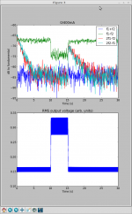
I've done other tests, still on the same amp.
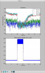
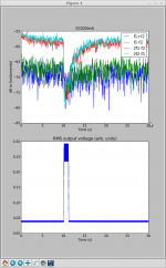
This time, the test signal is a 18k+19kHz intermodulation test, of constant amplitude (the current it creates in the 0.5 ohm load resistor is shown in the plot legend, 3 tests, at 100, 200 and 400mA RMS).
A sliding FFT is applied and the distortion products (shown in legend) are plotted on the top graph in dB relative to test signal fundamental. The x-axis is time.
The bottom graph shows output voltage RMS value (smoothed).
The 18k+19k signal is always running.
Between the 10s and 20s time marks, a low frequency signal is added to make the output push 1A RMS in the load resistor.
So, at the beginning, the amp is cool, and delivers maximum distortion (remember it is a bit underbiased).
The test signal alone starts to heat it a little, and the distortion products 2f1-f2 fall over a few seconds.
At t=10s, the low frequency tone heats the transistors a lot more. Distortion is much reduced.
At t=15s, low frequency tone stops. The amp cools down and distortion products rise again slowly over the next seconds.
The 1kHz intermod product (f1-f2) seems to obey different rules.
This shows that the traditional THD versus output power test also not very meaningful, unless one listens to constant power sine waves, since here in a few seconds the distortion has gone up and down by 20dB just by heating and cooling...
Making a high power THD measurement takes some time, so what is measured is THD on hot transistors. I suspect factors like "slam" or "speed" as often mentioned could relate to high power distortion characteristics on cold transistors, ie what happens on a transient coming after a quiet moment.
Similarly, after a loud passage the output transistors are hot, and once the music becomes quiet again, we hear low power distortion on hot transistors, but a low power THD test would measure it on cold ones, and miss target by 20dB here.
I've done other tests, still on the same amp.
This time, the test signal is a 18k+19kHz intermodulation test, of constant amplitude (the current it creates in the 0.5 ohm load resistor is shown in the plot legend, 3 tests, at 100, 200 and 400mA RMS).
A sliding FFT is applied and the distortion products (shown in legend) are plotted on the top graph in dB relative to test signal fundamental. The x-axis is time.
The bottom graph shows output voltage RMS value (smoothed).
The 18k+19k signal is always running.
Between the 10s and 20s time marks, a low frequency signal is added to make the output push 1A RMS in the load resistor.
So, at the beginning, the amp is cool, and delivers maximum distortion (remember it is a bit underbiased).
The test signal alone starts to heat it a little, and the distortion products 2f1-f2 fall over a few seconds.
At t=10s, the low frequency tone heats the transistors a lot more. Distortion is much reduced.
At t=15s, low frequency tone stops. The amp cools down and distortion products rise again slowly over the next seconds.
The 1kHz intermod product (f1-f2) seems to obey different rules.
This shows that the traditional THD versus output power test also not very meaningful, unless one listens to constant power sine waves, since here in a few seconds the distortion has gone up and down by 20dB just by heating and cooling...
Making a high power THD measurement takes some time, so what is measured is THD on hot transistors. I suspect factors like "slam" or "speed" as often mentioned could relate to high power distortion characteristics on cold transistors, ie what happens on a transient coming after a quiet moment.
Similarly, after a loud passage the output transistors are hot, and once the music becomes quiet again, we hear low power distortion on hot transistors, but a low power THD test would measure it on cold ones, and miss target by 20dB here.
Attachments
Last edited:
I did the CCIF test yesterday, with current injection to the output of the tested channel. Again, nothing special. The tested channel effectively reduces basic spectral lines and the rest is similar as distortion components - which is expected from the beginning. I assume these tests heavily depend on the topology and design of the amplifier under test.
Attachments
If your amp runs in overbiased Class-AB (as most do) then I guess self-heating in the output transistors is much less a problem...
It is "optimally biased" Class-AB (or underbiased) that will show large changes with self-heating.
I guess this is the reason why increasing the bias on an amp usually makes it sound better...
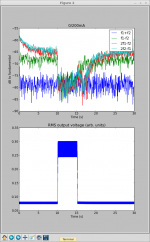
I wondered how much time was needed for the 1A current to heat the output transistors enough to affect the distortion : even with a 1s long pulse, the effect is clearly visible (see attachment).
Note that if I do a CCIF test on this amp here, with a long enough FFT like yours, I will get a "warm" measurement, so at least 20dB better than it actually is when cold...
It is "optimally biased" Class-AB (or underbiased) that will show large changes with self-heating.
I guess this is the reason why increasing the bias on an amp usually makes it sound better...
I wondered how much time was needed for the 1A current to heat the output transistors enough to affect the distortion : even with a 1s long pulse, the effect is clearly visible (see attachment).
Note that if I do a CCIF test on this amp here, with a long enough FFT like yours, I will get a "warm" measurement, so at least 20dB better than it actually is when cold...
Attachments
Last edited:
I have tried 'short bursts' of test signal and simultaneous measurement of HD and CCIF, and long continuous signal excitation. There is some fluctuation, but quite insignificant. I assume that overall robust construction is the main reason, together with quite high idle current.
> I assume that overall robust construction is the main reason,
> together with quite high idle current.
I'd assume high idle current is the main reason...
I did those tests mainly to see if such an effect could be measured, so I picked an amp that I suspected would exhibit it, precisely because it has low idle current.
I also wanted to play around with the python/numpy numerical analysis tools, which are quite impressive...
Thanks for that extensive, well above RD summary reply, Dan! I slightly mistood what you were aiming to do, but it's all good - because you basically described the concepts I used in my version of the classic gainclone; as you determined, getting to the heart of the matter of what really counts in making the electronics bits work as they're supposed to, makes all the difference to SQ. And, as you point out, the big, big headache is that it's very hard to experiment in the normal fashion - the concept either works or it doesn't, it lives or dies by its first iteration.I hope you can visualise from my description
This was an afternoon muck around to try proof of concept, lasted a week or so and then got canibalised.
Soldering to the CGP was one hell of a problem with the tools/equipment I had....that's why it got trashed....too hard to play with zobels or change any other components.
With the CGP some high weight copper clad pcb, and/or the right heating apparatus, this kinda idea ought to be sort of doable diy.
So the proof of concept was to see what an effectively infinite earth might do.....and the result was as predicted
With everything so solidly earth tied to each other, mono accuracy, stereo placement, and sounds from far away front and far away rear just apparitioned.
Absolute polarity became mission critical.
Having an electrically ideal earthing scheme does one thing......I feel that this sheer mass of very old, hundreds of times annealed laundry boiler copper did something extra...maybe.
Either way, the sound the sound was pretty darn clean overall, with magical accuracy of placement in left/right, and magical reproduction of sounds from in front and from the rear....3D !.....as should be expected.
Bottom line is that there was a most unusual solidity, and placement accuracy, and just plain pleasantness about the overall presence and sound image.
This was 15 years ago.....soonish I will take this concept major levels beyond what I had and see what I get this time !.
Dan.
As you state, taking this level of care gives excellent soundstaging - what I added was an extremely stiff power supply - 95% of the volume of the whole unit was power supply. This achieved a stability of tonality, it was invariant with volume - the only sign that limits were reached were that the inbuilt chip protection started to cut in, from overheating. Particularly amusing, you could pull the mains plug from the wall, and at moderate listening levels nothing would happen for about 5 minutes, music was still perfect until suddenly the last bits of reserve energy evaporated ...
Cheers,
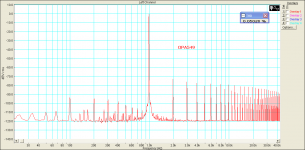
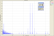
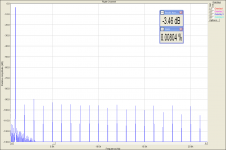
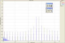
I have made the same test, with current injection, on the TI OPA549 power chipamp.
Operational Amplifier (Op Amp) - Precision Amplifier - OPA549 - TI.com
First, let's see 1k harmonic distortion FFT.
Operational Amplifier (Op Amp) - Precision Amplifier - OPA549 - TI.com
First, let's see 1k harmonic distortion FFT.
Attachments


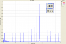
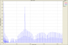

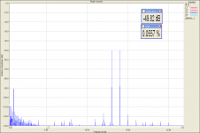
Then, 13+14kHz CCIF. So this is the chipamp, with low idle current and low slew rate.
wow !- Status
- This old topic is closed. If you want to reopen this topic, contact a moderator using the "Report Post" button.
- Home
- General Interest
- Everything Else
- Listening Test... A Practical Demonstration That Amplifiers Have Their Own Sound.