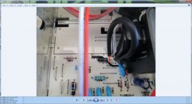
I just pulled PNP TR1002, tested it and it came up OK? Ive replaced C1002 as well,it read OK but I replaced it anyway.TR1005 is OK as well.When this sparking started it was across R1017 to start with and has since migrated to D1012,up to C1023 and back to D1012 next to the fly back transformer. What do you mean by pre=set? is that a resistor? If it is what sizes should I start with to do it manually?
No the neon's don't light now,they used to? I took the FET out but it made no difference at all? This service manual has got that many mistakes in it that its starting to do my head in Mooly. I might give it a rest and try those resistors tomorrow and get back to you with the results.Thanks for all the help so far mate its appreciated.
I might give it a rest and try those resistors tomorrow and get back to you with the results.Thanks for all the help so far mate its appreciated.Its no problem, faults like this are very difficult at a distance ")
I asked about the neons because they are an overvoltage clamp, so if not lit it suggests the EHT isn't excessive.
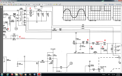
You need to investigate why the FET + PNP transistor is apparently having no effect on things. The PNP transistor should drastically alter the EHT as its conduction alters, and using the preset resistor across D-S of the FET would do that.
Lets just recap on this to be sure. FET in or FET out and there is no change ? FET shorted D-S no change ? If that is so then I think replacing that PNP is next on the list as well as checking all around that stage for breaks in continuity etc. At a basic level turning that PNP on and off has got to have a drastic effect.
I asked about the neons because they are an overvoltage clamp, so if not lit it suggests the EHT isn't excessive.
You need to investigate why the FET + PNP transistor is apparently having no effect on things. The PNP transistor should drastically alter the EHT as its conduction alters, and using the preset resistor across D-S of the FET would do that.
Lets just recap on this to be sure. FET in or FET out and there is no change ? FET shorted D-S no change ? If that is so then I think replacing that PNP is next on the list as well as checking all around that stage for breaks in continuity etc. At a basic level turning that PNP on and off has got to have a drastic effect.
Ive been following the tracks trying to work out what is going on here when I realized the first 2sk340 datasheet I had downloaded had given me the wrong pin-out? That's why I was so confused,I know you said it was like for like but I didn't think that a datasheet could be wrong? So its soldered back in the right way and now its sparks in rapid succession at turn on,(like in-rush current)then settles down and doesn't spark again at all at the moment. The spark goes from D1012 cathode through the zig zag hole in the board to the soldered side and occasionally across to the black wire on the fly-back transformer.One neon light stays on for a while with a dull orange light and the other lights up only when it sparks? The screen still looks the same,the only difference is the trace appears at the top or bottom of the screen every time its turned on.Sorry about my mistake.
Attachments
Last edited:
That all sound like excess voltage. The PCB cutout is in anticipation of that, the normal working voltage is getting to the point where it needs air spacing for reliability.
So we are back to excess EHT and seemingly no control over it. You need to try the resistors to turn on that PNP (replace it to) and see if that alters things.
So we are back to excess EHT and seemingly no control over it. You need to try the resistors to turn on that PNP (replace it to) and see if that alters things.
That all sound like excess voltage. The PCB cutout is in anticipation of that, the normal working voltage is getting to the point where it needs air spacing for reliability.
So we are back to excess EHT and seemingly no control over it. You need to try the resistors to turn on that PNP (replace it to) and see if that alters things.
OK Ill do that and get back on how it went?
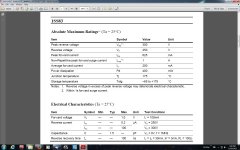
The high voltage tester still hasnt arrived (lost in the post) so they are sending me another one? I ordered two FETs,they've arrived so I installed one but it made no difference it started sparking from D1012 like crazy. I desoldered one pin on all the resistors and diodes around the circuit to check them all properly and found ISS83 D1024, is out of speck it reads on DMM diode setting out of circuit,.410 forward and .980 backwards! So maybe that was bouncing the voltage back to D1012? Now I'm going to have to find an equivalent for ISS83? Do you think a IN4001 would be OK? PS Happy New Year!!
That diode is definitely faulty with readings like that. Its also high speed high voltage type. Something like a BA159 would be OK (same package as a 1N4001). The 4001 is only 50 volts but even the higher voltage versions such as 4004's are not fast enough. This part of the circuit is working with the fast rise time high frequency flyback transformer derived voltages.
And happy new year
And happy new year
That diode is definitely faulty with readings like that. Its also high speed high voltage type. Something like a BA159 would be OK (same package as a 1N4001). The 4001 is only 50 volts but even the higher voltage versions such as 4004's are not fast enough. This part of the circuit is working with the fast rise time high frequency flyback transformer derived voltages.
And happy new year
OK it looks like this is the problem then? Here is the datasheet for the ISS83 Diode.I can get UF4004, 400v,1a,ultrafast diode would that do the trick?
Last edited:
If the UF device is a fast diode then yes, it should fine. These high speed versions have appeared decades after the original devices came on the market, and I have never used them tbh.
OK Ill get one,install it and get back to you on how it went.This year for sure LOL.
Attachments
Last edited:
On my old Hitachi scope the diodes around the HT supply are all ceramic types. Not plastic moulded like the 1N and UF series.. Looks like a slightly elongated ball and dull white in colour With rather thick leads.
UF1007 seems to have almost 10 times the capacitance and 5 times the turn off time !
Maybe MUR160 might work ? Low capacitance and fast recovery.
UF1007 seems to have almost 10 times the capacitance and 5 times the turn off time !
Maybe MUR160 might work ? Low capacitance and fast recovery.
Last edited:
On my old Hitachi scope the diodes around the HT supply are all ceramic types. Not plastic moulded like the 1N and UF series.. Looks like a slightly elongated ball and dull white in colour With rather thick leads.
UF1007 seems to have almost 10 times the capacitance and 5 times the turn off time !
Maybe MUR160 might work ? Low capacitance and fast recovery.
The ISS83 diode is glass encapsulated,my oscilloscope is a Protek 6502 not Hitachi and I was talking about the UF4004 not the UF1007? The UF4004 has half the recovery time and the same capacitance.I hope that clears things up?
Last edited:
On my old Hitachi scope the diodes around the HT supply are all ceramic types. Not plastic moulded like the 1N and UF series.. Looks like a slightly elongated ball and dull white in colour With rather thick leads.
UF1007 seems to have almost 10 times the capacitance and 5 times the turn off time !
Maybe MUR160 might work ? Low capacitance and fast recovery.
They sound like the old glass passivated types such as for example BYT77.
Ive replaced all the ISS83 diodes with UF4007s,D1012 with its equivalent and the 2SK304 FET. I turned the scope on and got arcing again? I switched it off immediately and used a dim bulb tester with a 75 watt bulb,switched it on again and everything was OK? So I plugged it back into the mains and no arcing at all this time? I did the voltage tests and everything came up normal.I left it until the next morning to calibrate the scope but when I turned it on it started arcing in the same place again? All this time the scope hadn't been moved? I seem to have an intermittent short somewhere that I cant find? Ive just about had it with this scope Ive spent day after day checking everything over and over and all I find is the service manual doesn't match what I have here in front of me? Different resistor/cap values etc...What on earth could cause this scope to act up like this?
Attachments
I just re read most of the posts from the beginning again.
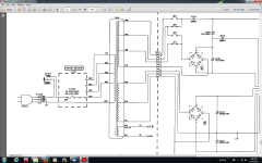
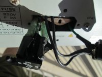
Are we 100% sure that the transformer voltage setting is correct. You mentioned it arrived with the selector damaged, the tranny gets really hot...
Are we sure on this.
Yes I'm fairly sure its set on 230volts because the yellow line is 230volts and that's what its connected to yellow (230v) and brown (100v)? The brown wire is connected to the other side of the fuse and isn't adjustable? So what that's about I don't know?
Attachments
Last edited:
The only way I can safely measure any voltages is to power it on with a dim bulb tester and then Ill get a lower voltage reading than what it should be. I'm starting to suspect the mains EMI filter box is shorting against the case because its loose, it must've been connected to the power inlet module? The trouble is Ill have to nearly completely disassemble the whole scope to get at it.Whats the chances of that shorting?That's clear enough I suppose although its worth measuring the 6.3 volts (AC) heater winding as confirmation. It should be pretty to close to that value (5% or so)
- Status
- This old topic is closed. If you want to reopen this topic, contact a moderator using the "Report Post" button.
- Home
- Design & Build
- Equipment & Tools
- Oscilloscope repair?