Might be worth checking that the supply feeding the EHT generator is correct. If that is high then the EHT will be high as well.
OK will do,Ill get back with the result.Ive got to put a few things back together again.
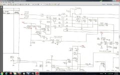
Ive been studying the service manuals for this scope ad nausium and Ive come to the conclusion that the Japanese are still fighting world war 2 through their service manuals I think FET 2sk340e may have failed,Ive looked for a datasheet for it without success,to see if I had a sub in my junk collection.Whoever wrote these manuals up wasn't too vigilant with the brackets to mark the voltages for the 20mhz scope,it looks like they've been left out in half the cases? Its made it so confusing trying to work out whats what with this thing.I downloaded a total of 8 service manuals in one download from Elektrotanya and not one of them shows the correct timebase PCB board? Heres a few voltages Ive done to see if anyone can work out whats happening here?
I think FET 2sk340e may have failed,Ive looked for a datasheet for it without success,to see if I had a sub in my junk collection.Whoever wrote these manuals up wasn't too vigilant with the brackets to mark the voltages for the 20mhz scope,it looks like they've been left out in half the cases? Its made it so confusing trying to work out whats what with this thing.I downloaded a total of 8 service manuals in one download from Elektrotanya and not one of them shows the correct timebase PCB board? Heres a few voltages Ive done to see if anyone can work out whats happening here?Attachments
Its hard to say tbh. If yours is the version that should have those higher voltages then it looks OK.
The FET and other transistor are part of the voltage feedback control circuit for the E.H.T. generator. Its strange to measure zero volts on those devices though. Any problems here could cause low or high E.H.T. (your sparking earlier). Is that supply marked +0 OK Check all the high value resistors, make sure non are open circuit.
Lets think how it works... its a self oscillating stage. The FET and next transistor are turned on, then as the NEGATIVE EHT builds, that pulls the gate lower and tries to turn off the FET. So it stabilises at some preset value of E.H.T. If the FET and transistor aren't working then the stage runs flat out... to much EHT.
You could be on to something... you need to check all the resistors and those two control transistors. If the FET was duff I would still expect to see some voltages around there... maybe recheck. I suspect many common devices could work for the FET such as 2N3819 etc.
The FET and other transistor are part of the voltage feedback control circuit for the E.H.T. generator. Its strange to measure zero volts on those devices though. Any problems here could cause low or high E.H.T. (your sparking earlier). Is that supply marked +0
OK Check all the high value resistors, make sure non are open circuit.Lets think how it works... its a self oscillating stage. The FET and next transistor are turned on, then as the NEGATIVE EHT builds, that pulls the gate lower and tries to turn off the FET. So it stabilises at some preset value of E.H.T. If the FET and transistor aren't working then the stage runs flat out... to much EHT.
You could be on to something... you need to check all the resistors and those two control transistors. If the FET was duff I would still expect to see some voltages around there... maybe recheck. I suspect many common devices could work for the FET such as 2N3819 etc.
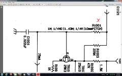
FET 2sk340e is now shorted on all pins? The other transistor is OK. I have some 2n7000 N channel FETs would they be OK to use? Ive been checking all the resistors,none have gone high,R1001 is 1.43M ohms on the schematic and either 1.73Billion ohms or 5.73Billion ohms going by the colors on it?????? It reads 8k ohms in circuit another 10m ohm resistor reads 7k in circuit,should I unsolder a leg on these ones that read low to measure them? I rechecked the voltages and I'm still not getting anything around that area,it must be the FET then?
Attachments
Last edited:
The 2N7000 is a power FET, like a small IRF240 in its characteristics. The diagram shows a JFET. That doesn't mean it won't work but I wouldn't like to guarantee how it would behave.
Is the FET reading short out of circuit ? If so then tie the gate to either of the other lead, D or S and with the DVM black lead on the two tied leads read the resistance of the device again. Does it still read short circuit ?
If you try the 2N7000 then you must fit it as marked, however most JFETS (the original) are symmetrical and D and S are interchangeable.
You need to isolate the resistors to read them.
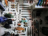
The FET reads shorted out of circuit and reads 17 ohms across from the negative black lead on the tied pins to drain in the middle.I live next to the sea as you can see by the alligator leads.Ill de-solder the high value resistors to check them out of circuit and then try the 2n7000 to see what happens?
Attachments
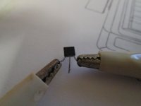
With your meter connected across the FET like in the picture (make sure it is across D and S) does the 17 ohms reading change if you now keep touching the gate with your finger. If it reads 17 ohms all the while then its faulty.
Yes,I tried that and its faulty alright. Ill get back when Ive checked those resistors and installed the 2n7000 to see what happens?
Remember to check the two series resistors that connect the gate of the FET to the negative E.H.T. rail.
The resistors read OK.I installed the 2n7000 and its back to square one, After about 5 minutes after turn on I get a spark across C1023 near the flyback transformer.its been doing this before I installed the new FET? Actually it seems to be a bit better now because I tried to set the astig with little round ball in the center of the screen and it was nearly round this time!
Last edited:
This sparking is a worry because it could well be pointing to excess E.H.T. There is no easy way to check this with a normal DVM. If you have a meter that can safely read up to say 3 or 4 kv then you could see what is across caps C1013 and C1014. All we can say for sure with those is that as they are 2kv rated and so you should see well under that across them.
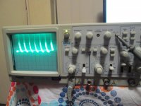
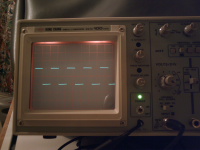
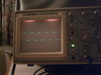
The calibrate signal should look like this. Notice in the first picture only the amplitude is correct. Scope on 0.5 volts/div and the cal output is 1 volt pk/pk. So the signal is two squares high. The horizontal axis is set to 0.5ms/div and so the nominally 1kHz cal signal gives 5 complete cycles (1kHz has a period of 1ms) but as the cal signal is not intended for timebase calibration its not super accurate. The second picture is exactly 1kHz from a generator and you can see that the timebase is in fact correct.
The calibrate signal should look like this. Notice in the first picture only the amplitude is correct. Scope on 0.5 volts/div and the cal output is 1 volt pk/pk. So the signal is two squares high. The horizontal axis is set to 0.5ms/div and so the nominally 1kHz cal signal gives 5 complete cycles (1kHz has a period of 1ms) but as the cal signal is not intended for timebase calibration its not super accurate. The second picture is exactly 1kHz from a generator and you can see that the timebase is in fact correct.
Attachments
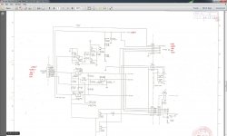
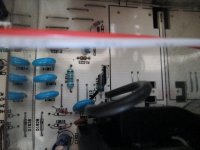
I just found 4 failed ISS83 diodes around the fly-back transformer,one is shorted the others aren't reading anything in or out of circuit.I'm wondering what I could use as a substitute? I tried to copy the ISS83 datasheet here but it doesn't work? The cheapest high voltage DMM probe I can find is on fleabay for $52 its a kit with 80, 10M ohm resistors to solder onto a board and that doesn't include a housing for it. I suppose its better than the alternative though.I live out in the middle of no-where Mooly and by the time I order some 10m ohm resistors etc...it would take the same time, so Id be better off getting the kit and some new diodes if I cant find a sub for them in the mean time.The other diode is hidden under the wire going across the photo.
Attachments
Just found this while looking for the ISS83.
http://www.diyaudio.com/forums/equipment-tools/226979-oscilloscope-repair-diode-id.html
The diodes in your picture look to me like normal diodes and their location on your diagram suggests they are to. Normal but high voltage, probably high speed/soft recovery type too. Can't think of anything that small as a replacement off hand... BY399 type is a bit chunky, you would have to mount them under the PCB.
Ooops... only just realised you attached a data sheet. Yes, high speed diodes. Is the IN4007GP (must be GP) a high speed version of the common 4007 ?
WTF? I just measured those diodes again and now there all OK? I haven't changed anything except to discharge the elektro caps? The only thing I can think of is that I didnt disharge everyone of them just the big caps? Forward voltage is OK back voltage reads about 1200 ?
Last edited:
- Status
- This old topic is closed. If you want to reopen this topic, contact a moderator using the "Report Post" button.
- Home
- Design & Build
- Equipment & Tools
- Oscilloscope repair?