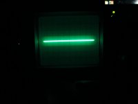
This is the line I'm getting just in case its a clue? Sometimes the glow around the line is missing? Ive measured the watts its supposed to be 35w for the 20mhz scope but I'm getting 45w.? I'm starting to think it maybe the fly-back transformer again? Ive checked everything else I can think of? Its back to sparking from the D1012 diode now,its not going across but its just there on the one pin? There could be something wrong with the BNC connector coz Ive tried 5 probes and they all seem to be wonky.I adjusted the trim on this one and got this in the photo.I turned the scope on and a spark went across both pins on D1012 this time?
Attachments
Last edited:
If there is doubt on the probes then just directly connect the centre of the BNC input to the cal output with a single piece of wire... all the grounding is taken care of internally.
The sparking has to be either the voltage jumping due to contamination or the voltage is to high. The single line trace doesn't seem to be filling the screen. Taken in isolation that could well point to the EHT (that's really everything derived from the flyback tranny) being high. High EHT makes the tube harder to scan for a given deflection voltage, result, a smaller trace.
Everything comes back to needing to know whether the tranny is operating correctly (I doubt its faulty) and the control circuitry around the FET.
Is there still zero volts around those two transistors ?
You could try as a test replacing the FET with a preset (say 22k as a guess ) between D and S and seeing if that allows control of the EHT. Is the rail marked +0v that goes to the middle transistor OK ? As the preset is lowered in value it will turn on the middle transistor and should reduce the EHT.
(It seems that the FET is normally biased on via the 120v supply and as such the EHT generator gives max output. As the negative EHT develops it pulls the gate more negative and so reduces the EHT. When equilibrium is reached the EHT is stable. The ratio of the resistors and voltage rails determine the exact final EHT value)
(It seems that the FET is normally biased on via the 120v supply and as such the EHT generator gives max output. As the negative EHT develops it pulls the gate more negative and so reduces the EHT. When equilibrium is reached the EHT is stable. The ratio of the resistors and voltage rails determine the exact final EHT value)
Hmmm... those 0.2 volt reading are enough to make me wonder if it is actually working after a fashion. They could well be dynamic low duty cycle AC signals.
Its all so difficult to prove.
I would think that with the FET out of circuit then the EHT stage would not start. It needs the FET turn on to pull the base of the PNP transistor low and supply DC bias via R1005 to the switching transistor. All that happens because of the gate bias resistors to the other rails... the FET is fully on. In that state the stage runs flat out... I think") ... which is max EHT. The FET lowers the EHT (stabilises it) by conducting when the gate feed via R1017 is sufficiently high (negatively) to pull the gate down and turn the FET off. That's the point stabilisation occurs and the EHT is at some predetermined value.
... which is max EHT. The FET lowers the EHT (stabilises it) by conducting when the gate feed via R1017 is sufficiently high (negatively) to pull the gate down and turn the FET off. That's the point stabilisation occurs and the EHT is at some predetermined value.
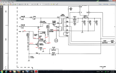
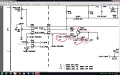
Where does the line to the right go, the one above C1020 ? Is that fed to the CRT grids, perhaps the astigmatism part of the circuit. Any marked voltages off that line that would give a clue as to whether it was correct or not ?
Its all so difficult to prove.
I would think that with the FET out of circuit then the EHT stage would not start. It needs the FET turn on to pull the base of the PNP transistor low and supply DC bias via R1005 to the switching transistor. All that happens because of the gate bias resistors to the other rails... the FET is fully on. In that state the stage runs flat out... I think
... which is max EHT. The FET lowers the EHT (stabilises it) by conducting when the gate feed via R1017 is sufficiently high (negatively) to pull the gate down and turn the FET off. That's the point stabilisation occurs and the EHT is at some predetermined value. Where does the line to the right go, the one above C1020 ? Is that fed to the CRT grids, perhaps the astigmatism part of the circuit. Any marked voltages off that line that would give a clue as to whether it was correct or not ?
Its a good point and I'm not sure how much difference that might make here if I'm honest. The major difference is that one (the depletion) is still conducting at 0v across gate and source whereas the other (enhancement) is fully off.
How the G-S junction behaves dynamically when fed the "rippley" EHT from across those 2kv caps... in raw numbers the FET is fully on at start up and has - ??? up to 2kv to turn it off. I would imagine the control loop should at least work to enable it to be proved.
How the G-S junction behaves dynamically when fed the "rippley" EHT from across those 2kv caps... in raw numbers the FET is fully on at start up and has - ??? up to 2kv to turn it off. I would imagine the control loop should at least work to enable it to be proved.
Your right, that's where it goes. All those ISS83 diodes are reading OK now. The big one 6kv D1012 doesn't read anything in and out of circuit,so I ordered some more equivalents and before I installed one I measured it and it wasn't reading anything either? I figure its got a high forward voltage that my meter cant manage? I keep forgetting to mention that the focus pot isn't working? Should I try bridging D & S on where 2sk340e was yet or wait?
Attachments
Last edited:
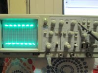
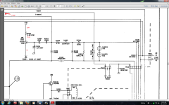
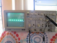
Heres a few more things that may help or confuse? The notes in the S/M say that the 20mhz model has the parts in brackets but this shows that I should have 15m ohms and a 1.5M ohm resistor instead of the 3.9M ohms I have here in both? Its the high tension line and says Danger on the S/M. Ive inadvertently measured it a few weeks ago and blew out my good DMM  Lucky I have a half decent spare to carry on with.Ha!.OOOH,The focus is working now,it must have been a tiny bit of solder across a couple of pins I found when I was looking for cracked tracks etc...The first photo shows the trace oscillating left to right and the AC one oscillates as if its expanding and contracting?
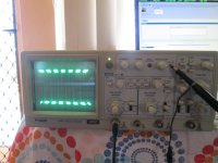
Lucky I have a half decent spare to carry on with.Ha!.OOOH,The focus is working now,it must have been a tiny bit of solder across a couple of pins I found when I was looking for cracked tracks etc...The first photo shows the trace oscillating left to right and the AC one oscillates as if its expanding and contracting?Attachments
Last edited:
The oscillating trace again points to EHT problems. If the EHT is "breathing" then the trace size will appear to fluctuate. True high voltage diodes can read oddly in the forward direction, as you say they have a higher turn on voltage.
The missing transistor could be something like spot suppression (when you switch off). If its missing by design I wouldn't worry
Its difficult diagnosing something like this at a distance. I tempted to say try adding a preset across D and S (10or 22k ish) and see if it seems to have control over the EHT. Don't alter it wildly because the oscillator may stall and draw high current but see if it "does something".
OK, Ill try that with a 15k resistor.Do I leave the FET in when I try it or take it out?The oscillating trace again points to EHT problems. If the EHT is "breathing" then the trace size will appear to fluctuate. True high voltage diodes can read oddly in the forward direction, as you say they have a higher turn on voltage.
The missing transistor could be something like spot suppression (when you switch off). If its missing by design I wouldn't worry
Its difficult diagnosing something like this at a distance. I tempted to say try adding a preset across D and S (10or 22k ish) and see if it seems to have control over the EHT. Don't alter it wildly because the oscillator may stall and draw high current but see if it "does something".
OK, that's maybe a wee bit high. Try going lower by degrees. At some point, if the middle PNP is working correctly then the EHT has to alter. We need to prove that.
A technicians trick if it were on the bench in front of me use a slightly damp finger tip and touch the gate and drain at the same time and see if you get any change in operation.
A technicians trick if it were on the bench in front of me
use a slightly damp finger tip and touch the gate and drain at the same time and see if you get any change in operation.If you use the finger trick I should have said G to S (its already on via the bias network) but just touching just the gate should do obvious things.
It doesn't do anything at all? Ive used 12k,15k and 22k resistors.I didnt use a wet finger though I'm **** frightened of that high voltage Ha! so I used a small screw driver on the gate and across D and S but nothing changes at all? What would be a common FET I could easily replace this one with ?
Last edited:
Lets just think where we are up too...
If shorting the FET out changes nothing then that either means the FET was already fully on to begin with ??? which would need around 4 volts across G-S for a 2N7000.
Do you have a small preset ?
If you take the FET out and fit the preset across D-S then you should be able to alter the EHT manually. Because you have already tried shorting the FET out, this time start with the resistance low and work your way up.
Alternatively... just remove the FET and note the effect. If there is still no change then that PNP transistor and/or the resistors or print around it is looking highly suspect.
- Status
- This old topic is closed. If you want to reopen this topic, contact a moderator using the "Report Post" button.
- Home
- Design & Build
- Equipment & Tools
- Oscilloscope repair?