Inspired by this thread that went a bit off topic, I decided to continue the part about oscilloscopes here and perhaps shredhead can continue this thread with the search for the cause of a dead channel on his Tek scope.
Here's my contribution to start this thread:
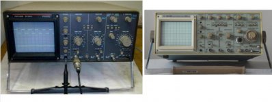
I have a fully functional Philips PM 3208 20 MHz oscilloscope which experienced dropouts in the connected signals. Touching the vertical scale knobs of both channels was enough to send the trace on the screen in all directions.
As suggested by anatech, I applied some contact cleaner to the innards of both rotary switches, but without spraying. Since these switches aren't sealed or shielded, I thought I'd go a step further and clean them with a cotton swab (Q-tip). However, access to the switches was largely restricted by a small pcb hanging over them. Unfortunately, I couldn't access all the screws without having to do a major dismantling job, something I wasn't looking forward to.
Instead, I decided to loosen the so-called "vertical board" (ironically mounted horizontally, it deals with the signals on the vertical axis) and move it back a couple of cm. That meant removing the transformer, desoldering the input AC-GND-DC switches, unplugging a lot of connectors and unscrewing a remarkable amount of ground leads from the chassis.
But in the end I managed to access the vertical scale switches and the black deposit came off rather easily, leaving a brass like colour. It was worth the hassle, the traces now remain steady when I touch the vertical scale rotaries. Job finished.
Below the rotary switches in all their glory.
Here's my contribution to start this thread:
I have a fully functional Philips PM 3208 20 MHz oscilloscope which experienced dropouts in the connected signals. Touching the vertical scale knobs of both channels was enough to send the trace on the screen in all directions.
As suggested by anatech, I applied some contact cleaner to the innards of both rotary switches, but without spraying. Since these switches aren't sealed or shielded, I thought I'd go a step further and clean them with a cotton swab (Q-tip). However, access to the switches was largely restricted by a small pcb hanging over them. Unfortunately, I couldn't access all the screws without having to do a major dismantling job, something I wasn't looking forward to.
Instead, I decided to loosen the so-called "vertical board" (ironically mounted horizontally, it deals with the signals on the vertical axis) and move it back a couple of cm. That meant removing the transformer, desoldering the input AC-GND-DC switches, unplugging a lot of connectors and unscrewing a remarkable amount of ground leads from the chassis.
But in the end I managed to access the vertical scale switches and the black deposit came off rather easily, leaving a brass like colour. It was worth the hassle, the traces now remain steady when I touch the vertical scale rotaries. Job finished.
Below the rotary switches in all their glory.
An externally hosted image should be here but it was not working when we last tested it.
Last edited:
Hi jitter,
Why not use a spray?
The fluid tends to get into everything. It changes the dielectric constant of the switch wafers and PCB for one. That changes as the fluid then moves or evaporates very .... very ... slowly over time.
This fluid also creeps into trimmer capacitors. May as well replace those now.
The fluid can creep into capacitors and transistors (yes, that can happen). Scrap those and replace.
Finally, the cleaner will often wash away any lubricants off of contacts and even shaft bearings. Ever felt a sloppy radio control? Thank the TV tech who sprayed it years ago.
Controls and switches actually require only a tiny bit of cleaner placed in the correct spot. The carpet bombing approach taken by most only destroys more than it fixes.
Ever want a chance to rebuild an entire front end in a 'scope? Easy, spray it. Yes, it will probably still work, but the calibration is almost surely out the window. Adjust it and you might find that this instrument will never "hold" its calibration.
I learned this a long time ago from an engineer who patiently taught me how to use chemicals. The one thing he stressed was that chemicals are tools. Use the right tool in the right way.
A can of spray cleaner is much like using a hammer to fix everything. Too bad this will work in the short term.
-Chris
Which is probably why people like to spray switches.However, access to the switches was largely restricted by a small pcb hanging over them. Unfortunately, I couldn't access all the screws without having to do a major dismantling job, something I wasn't looking forward to.
Why not use a spray?
The fluid tends to get into everything. It changes the dielectric constant of the switch wafers and PCB for one. That changes as the fluid then moves or evaporates very .... very ... slowly over time.
This fluid also creeps into trimmer capacitors. May as well replace those now.
The fluid can creep into capacitors and transistors (yes, that can happen). Scrap those and replace.
Finally, the cleaner will often wash away any lubricants off of contacts and even shaft bearings. Ever felt a sloppy radio control? Thank the TV tech who sprayed it years ago.
Controls and switches actually require only a tiny bit of cleaner placed in the correct spot. The carpet bombing approach taken by most only destroys more than it fixes.
Ever want a chance to rebuild an entire front end in a 'scope? Easy, spray it. Yes, it will probably still work, but the calibration is almost surely out the window. Adjust it and you might find that this instrument will never "hold" its calibration.
I learned this a long time ago from an engineer who patiently taught me how to use chemicals. The one thing he stressed was that chemicals are tools. Use the right tool in the right way.
A can of spray cleaner is much like using a hammer to fix everything. Too bad this will work in the short term.
-Chris
Hi jitter,
That is exactly how I clean contacts. Some times you need to use a strip of business card or paper. Cutting off 50% or so of the Q-Tip makes it easier to clean the contacts without getting the Q-Tip stuck in those contact "fingers". If you do that, carefully rotate the switch the other way while pulling very lightly on the Q-Tip. It should feed out without damaging the contact finger. If not, be careful and patient! Bending these fingers can often spell disaster as that connection may never be reliable again. Take it from someone who was patient one day. I'll remember that incident. Thank goodness it was my equipment (which is probably why I wasn't careful).
I'm really happy this worked for you jitter. Thank you for beginning this thread and posting your work. I almost recognize that 'scope. It is very similar to many others I have worked on.
-Chris
Hi jitter,
I almost recognize that 'scope. It is very similar to many others I have worked on.
-Chris
Today, I also cleaned the timebase rotary switch, it's as good as new now... well almost...
Here are pictures of top and bottom to jog your memory
") :
:An externally hosted image should be here but it was not working when we last tested it.
An externally hosted image should be here but it was not working when we last tested it.
Last edited:
Hi jitter,
That is a nice clean interior. It strikes me as a really nice little backup 'scope. I probably worked on a similar model at some point. It does look familiar ...
Now that you have spent a little time (and very little cleaner), this little fella should be back up and running.
-Chris
That is a nice clean interior. It strikes me as a really nice little backup 'scope. I probably worked on a similar model at some point. It does look familiar ...
Now that you have spent a little time (and very little cleaner), this little fella should be back up and running.
-Chris
That's a good looking scope on the inside. Most old beasts aren't so clean anymore. The nice thing about the old analog ones, is that they have switches that you can actually clean and get working again. My woes are with a Philips/Fluke PM3384A. It has rotary encoders and push buttons for everything, and relays in the front end for vertical range switching. And you guessed it... It has a bad relay and a bad encoder. The relay may still be obtainable on Ebay, but I am out of luck with the encoder, it seems impossible to find an encoder that fits. Opening the encoder for cleaning, and then successfully re-assembling it is almost impossible. So my only hope is to find someone with a broken 'scope that has the same encoders as mine. Anyone?
Good work with the repair
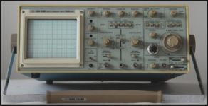
The mechanical layout of that scope is almost identical to my Hung Chang 100MHz one. I pulled some images of the Philips front panel and it looks very similar in layout. These have come out of the same factory methinks
I thought the same about the layout of Tek's 22xx scopes:
An externally hosted image should be here but it was not working when we last tested it.
Similar in layout perhaps but the knobs and switches look different. Compare the Philips with the Hung Chang and there is a huge similarity. The position and style of the timebase controls (lower right) and the position and layout of the trigger controls and yellow trig LED are a giveaway. The Philips looks to have a much better mains switch though. Screen bezel... same. Follow a horizontal line through the main controls... same. It will be the same chassis in all probability.
Attachments
Hi Mooly,
Hung Chang seems to have been the OEM of choice for many. The Tektronix is a little different on the inside though. They even have their own failure mode! The leads on the triac are push-on. Oops! Should have been soldered.
I had a Tetronix 2213, gave it to a friend who needed a scope and had nothing. The Tek is treating him well I hear. I originally bought that one not working to use it's knobs to repair a 2235. Couldn't resist the urge to fix the 2213, and darn! I did fix it. The 2235 is still sitting here. It will donate parts with my other 2235 in case it breaks down.
-Chris
'Their own failure mode' I think that could be said of many products
I've had the Hung Chang many years now, but its not been totally trouble free. Around 18 months ago the X amp output stage started playing up and needed new output transistors (and I replaced the drivers for good measure).
Tektronix, Kenwood/Trio and latterly Hitachi were standard issue at work back in the day... the itchyscratchis were good too.
Similar in layout perhaps but the knobs and switches look different. Compare the Philips with the Hung Chang and there is a huge similarity. The position and style of the timebase controls (lower right) and the position and layout of the trigger controls and yellow trig LED are a giveaway. The Philips looks to have a much better mains switch though. Screen bezel... same. Follow a horizontal line through the main controls... same. It will be the same chassis in all probability.
You're right. I found the Hung Chang twin to the Philips PM 3208, it's the 5502.
This looks almost identical, but there are a few small differences. The already mentioned mains switch, in the Philips, this is located at the back and operated by a long rod. The printing on the front is slightly different and there's a power LED on the Hung Chang that the Philips annoyingly doesn't have.
But how about the internals? Are they the same?
Last edited:
Hi Mooly,
Could be. I am working on a Hung Chang right now (Ramsey). It has a Z axis fault. The intensity control does not affect the beam intensity, but the voltage is changing with control position. I put it aside for a bit until I get a flash of insight. I think the grid is open.
-Chris
Could be. I am working on a Hung Chang right now (Ramsey). It has a Z axis fault. The intensity control does not affect the beam intensity, but the voltage is changing with control position. I put it aside for a bit until I get a flash of insight. I think the grid is open.
-Chris
Hi Mooly,
Could be. I am working on a Hung Chang right now (Ramsey). It has a Z axis fault. The intensity control does not affect the beam intensity, but the voltage is changing with control position. I put it aside for a bit until I get a flash of insight. I think the grid is open.
-Chris
Hmmm... that sounds a bit strange.
There is another Hung Chang thread on the go here,
http://www.diyaudio.com/forums/equipment-tools/266277-oscilloscope-repair-6.html#post4267864
which is turning into a bit of a marathon. One problem is an inoperative brightness control. The other is intermittent flashover and arcing on some components on the PCB. I wonder if its something similar to what you suspect on yours.
Hi jitter,
You have the skills to add a pilot light. Why not go blue, just to be different?
-Chris
True, I could, but nowadays I'd tend NOT to use blue to be different
.Hi jitter,
I was kidding you on that. You could use a warm white, hardly conducting. They look close to instrument lamps when lit low.
- have drill, will travel! - Arrrrr Billy! Ever been to sea before laddy?
Hi Mooly,
That sounds like my problem. The trace is pretty bright and will not change at all. The arcing and flashover sounds like it is either got contaminates on the boards, or the HV is adjusted to be too high. You need an HV probe for that work (got one).
Thank you for the link, I'll check it out.
-Chris
- Status
- This old topic is closed. If you want to reopen this topic, contact a moderator using the "Report Post" button.
- Home
- Design & Build
- Equipment & Tools
- Oscilloscope woes