@Shinja,
The dif input resistance of the 2625-5 is some 300M ohms. The input dif resistance of an
lm4562 AKA LME49720 is 30k ohms. Big difference there. I would concerned about the loading on the notch network by the A3QA1. You might have to increase C27 from 5pF to something more if it doesn't effect the bandwidth of the amplifier. The LM4562 would not be my choice for this amplifier. The current noise iis relatively high compared to the original op amp. 2625-5 is 0.16pA/rtHz. The LM4562 is 1.6/3.1pA/rtHz 10H/1kHz. I would expect
worse performance in the lower frequency ranges with 549k to 4.3M ohms. Even though the noise voltage of the 2625-5 is 7nV/rtHz the current noise of the 4562 will exceed this.
My 2 dollars, due to inflation.
I also tried to replace A3 QA1 to singled LM4562 to reduce residual noise further.
I expected replacing it may affect amplitude response upper notch frequency.
The amplitude response did not differ by the mod ,but the opamp weakly oscillate when inputting some specific frequencies such as 997Hz .I don't know why!oh no.
The oscillation occurs after top and bottom portions of swing.
Right where the current is highest.
You might also try decoupling the output of the op amp with a 10 ohm resistor.
David,
Differential input impedance is bootstrapped by opamp itself thus it does not become much heavy load at bridged T output.
In addition, current noise goes through the bridge cap above the notch frequency so it affect SN more at higher notch frequency.voltage noise is more important at lower notch frequency.
Estimating noise is difficult for me due to positive feedback and latter notches.
So I used LTspice.In summary,LME49710 is not best opamp there, but it is still worth changing.
Unexpectedly, differential input impedance is not negligible for residual noise.
I have not look into oscillation problem yet.
Differential input impedance is bootstrapped by opamp itself thus it does not become much heavy load at bridged T output.
There is no such situation.At 5Hz,lowest frequency of dist mesurement, each bridge resister is 55kΩ//220kΩ.I would expect worse performance in the lower frequency ranges with 549k to 4.3M ohms.
In addition, current noise goes through the bridge cap above the notch frequency so it affect SN more at higher notch frequency.voltage noise is more important at lower notch frequency.
Estimating noise is difficult for me due to positive feedback and latter notches.
So I used LTspice.In summary,LME49710 is not best opamp there, but it is still worth changing.
Unexpectedly, differential input impedance is not negligible for residual noise.
I have not look into oscillation problem yet.
Attachments
Last edited:
I have found that national LME49xx op amps enjoy a bit more FB capacitance up to 30pF.
There seems to be a bit of high frequency peaking which doesn't always show up in the models.
I tried many different op amp in my ST oscillator. The 49710 raised the noise by 4-5dBV.
The LT1468 won over all else tried for both noise and distortion.
There seems to be a bit of high frequency peaking which doesn't always show up in the models.
I tried many different op amp in my ST oscillator. The 49710 raised the noise by 4-5dBV.
The LT1468 won over all else tried for both noise and distortion.
Last edited:
has anyone ever actually measured the distortion level of the LT1468?
Yes Samuel Groner has. It's in his Operational Amplifier Distortion paper.
He used the dual version LT1469 for evaluation. The LT1468-2 uncompensated version didn't
as well.
Yes Samuel Groner has. It's in his Operational Amplifier Distortion paper.
He used the dual version LT1469 for evaluation. The LT1468-2 uncompensated version didn't
as well.
'The LT1468-2 uncompensated version didn't do as well.'
Maybe you Gent's can help me read the meter.
I'm referring to Richards post here, #239.
Trying to read the Shibasoku meter properly.
From what I understand of it being:
switched on, with the analysis gain ( -10dB)
.0003%
-110 dB
AND
we read the meter's needle as
2.5 for percent, -13dB, then do we add it to the
.0003 +.00025 = .00055%
and -110 + -13 = -123 dB.
One finally arrived which I got mine from an acquaintance and it seems to work just fine.
Now I understand why you guys like it so much. Almost like something Ron (popiel) would sell as in you just "Set it and forget it". No fiddling about with tuning knobs
etc. All the relays are kind of unsettling the first time you hear them tuning in
auto mode.
I can also understand why these might be used in manufacturing too, they
are fast and you can test a lot of devices quickly.
You can bet that I'd like to make mine a little bit better too,
using some modern opamps and parts if needed.
Let me know what y'all have been cooking up and
I'll take care not to go too crazy. No more waterboarding for me.
Hope y'all have a great weekend.
It's probably easiest to use the percent scale which ranges from 10 FS down to 0, 0 to 100%
If the meter reads 10 and your range is set to -90dB (0.003%) then a reading of 1 on the meter is 10% of 0.003% = 0.0003%. You can measure down to 1% on the meter quite accurately. The normal monitor output is scaled exactly the same as the meter.
A reading of 10 on the meter is 1Vrms on the normal monitor output for any range.
On the Analysis monitor output you have the option to add 10dB of gain to the meter. This gives you -10dB more range. So you can measure down to -100dBFS.
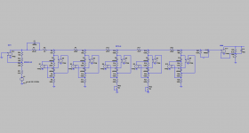
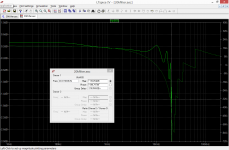
725C optional 20kLPF
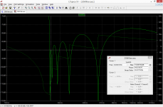
11th elliptic? but ripples are far from ideal.
and NOISY! I replaced TL071 and LF356.
What did you replace them with?
What was the result?
Cheers,
TL071 to 5534 it may not be enough slew rate so I will replace something later.
LF356 to OPA627 haha it's too pricey opa from LF356 but I do not have suitable opa here now.
I did not recorded measurement result but residual noise go down at about 1-3V input range in which input ALC amp is low gain.
I will try to replace uPA61A of input amp to something.
LF356 to OPA627 haha it's too pricey opa from LF356 but I do not have suitable opa here now.
I did not recorded measurement result but residual noise go down at about 1-3V input range in which input ALC amp is low gain.
I will try to replace uPA61A of input amp to something.
Last edited:
What is it about the uPA61A that you would want to try a different part?
I built the circuit in sim and didn't find much difference in noise or distortion between jfet models.
The Jfets are just buffers. They are connected in darlington with the bipolar input transistors.
I built the circuit in sim and didn't find much difference in noise or distortion between jfet models.
The Jfets are just buffers. They are connected in darlington with the bipolar input transistors.
David, you are right.
I looked schematic. uPA61A looks biased about 1mA so gm is 2.5mS and equivalent noise resistance is circa 260ohm.
that is much smaller than R2 1.5kohm even in LTP = 520ohm.
R2 must be bypassed if we pursue more SN here but that is trade off of protection.
How do you think bypassing with little light bulb as AP uses in their system one?
David, you are right.
I looked schematic. uPA61A looks biased about 1mA so gm is 2.5mS and equivalent noise resistance is circa 260ohm.
that is much smaller than R2 1.5kohm even in LTP = 520ohm.
R2 must be bypassed if we pursue more SN here but that is trade off of protection.
How do you think bypassing with little light bulb as AP uses in their system one?
Yes I think you can use a lamp there. But check to see if the distortion up.
I like to stay in the 3V range for SNR as you pointed out. A lamp would also act as a fuse. Fuses tend to raise the distortion so a lamp might be better in this regard.
I'm not sure if using a lamp will do much for noise because of the very high input Z of the jfet gate. It's worth a try.
The clamp circuit is there to satisfy a law that says test equipment must be able to withstand 300V input without harming the user. The HP 339A uses the same circuit but with different parts to do the same function. IIRC they used 500 ohm resistor but I'd have to look to be sure. I think HP also used an input fuse.
I played around with the source resistors and CCS current in sim but the noise seems to be just that of the Jfets + a small amount of resistor noise. Not nearly as much from the resistors as I first suspected.
let me know how it goes.
Lamps work great. There is no current if the lamps are implemented correctly. The resistance changes something like 3X to 5X between off and on in a desirable direction. The lower resistance will remove a limitation. The challenge I had was finding smaller 240V lamps to handle a 300V max input in the Boonton. PC mountable 2-5W 120V lamps are not difficult to find in the US and would probably work fine. On a manual ranging instrument getting the circuit right is more important. The autoranger should switch ranges quickly enough to never stress the lights.
The noise floor of the Shibasoku is around 5 nV and getting lower may be way too difficult, requiring a lot of changes to feedback impedance etc. with unknown consequences. I looked at really low noise JFets for the input in simulations and it did not make much difference.
The 20 KHz low pass filter is between the input amp and the notch filters so its distortion contribution becomes a limitation. I suspect opamps improvements won't help if its a Sallen-Key filter.
A couple of 120V lamps in series would do it. But I agree with you on the noise thing. Not much to gain there. The 20kHz filter on 725C is switchable so distortion from that is optional.
The 20kHZ filter is on the same board with all the other filters. Pretty wild routing.
The 20kHZ filter is on the same board with all the other filters. Pretty wild routing.
Last edited:
I tried putting little 12V lamp on 1.5k resistor which is DCR=20ohm at room temp.
At first look, residual noise reduces around 2dB at low input range, yeah as expected.
When testing at some input frequency at upper limit of amplitude range , the distortion rises irregularly. aaaah it is oscillating.
I experienced similar phenomenon when I trid to replace a notch opamp. I checked oscillation at notch output only at the time but not input. i must confirm what was oscillating.
The 20ohm may be too low, though the differential input capacitance between JFETs gate to gate must very small?
singal source I used is 600ohm output impedance.
725C's *20k* filter is on the other board inserted between 3rd notch and filter board switched by relays on the mother board.
Fundamental wave is attenuated before it so distortion do not matter.
In simulation the residual noise is 77uV up to 30kHz BW ,which is -118dB of 3.16Vinput*2gain*10gain.
I'm curious about this observed oscillation. Are you sure it is oscillation and not an ingress signal. Is it in any way related to the change at the input with the lamp?
The circuit formed by Q2 and Q2 has a dual purpose. It keeps the the Ac potential across the Jfets relatively equal which nulls the effect of the nonlinear
junction capacitance of the Jfets. The circuit does the same for the input protection diode circuit by keeping the AC potential equal across the diodes D4 and D5. This nearly eliminates the leakage current through the diodes. Two sources of distortion are eliminated or minimized. Effectively there is no capacitive reactance other than strays at the input amplifier. So what effect if any would a change of input resistance have in this range?
Last edited:
- Home
- Design & Build
- Equipment & Tools
- ShibaSoku Automatic Distortion Analyzer