4 zeroes and a 1.That's certainly in the ball park !!
Cant wait to measure it here and get pcb built and stuffed into something.
Thinking about writing/publishing an article?
--Richard Marsh
Hi Rick,
I not much of technical writer. But if some else wants to write it up I'll do the footwork.
To get distortion this low the output must be unloaded as much as possible. A good low distortion buffer is required. Op amps just don't have the drive current available. I know the LME's go to 600 ohm but I just don't like them.
Most SVO's I've seen run well below 3Vrms. The distortion drops in more than linear way below this threshold. I need to run it higher for now so I can see the distortion.
Cheers,
Last edited:
I would not worry about 600 Ohms..... a legacy relic of a bygone era. And opamp buffer will be fine for those 600 Ohms equipment. Or do as Krone-Hite does.... have an output directly off the osc and another output thru a buffer for low Z drive.
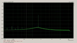
The K-H 4402B does 4 zeros and a 5 (with a few changes). Victor's is about half that. At 1KHz.
What does your design do at 10KHz?
Thx-RNMarsh
The K-H 4402B does 4 zeros and a 5 (with a few changes). Victor's is about half that. At 1KHz.
What does your design do at 10KHz?
Thx-RNMarsh
Hi Demian,
To answer these questions one of us has to build these circuits and test them. I'm kind of busy with my current project.
Cheers,
I'm ready to build and test some filter options. I would like some direction if anyone has explored this earlier. Which types and implementation details would be very helpful.
I'm ready to build and test some filter options. I would like some direction if anyone has explored this earlier. Which types and implementation details would be very helpful.
Hi Demian,
A tracking SV is what I would play with, A while back Samuel posted a 4th order SV oscillator. The design equation are available from Rane's website. It has a high sensitivity to matching elements of the tuning but that was with an un damped filter. There are four sections to tune.
It gives a nice 24dB LP. It provides quadrature outputs in all 4 phases. So a quadrature rectifier is probably the way to go with a mass of filtering or you can try the idea I suggested. If you want to go that route. Otherwise it's more sophisticated control like what Bob used in his analyzer.
What we need to know is how well the filter does with various tuning elements. For that a control system is not required, No point in developing one if the basic idea is flawed.
With that said maybe try some different filter types, SV, Wien etc. VCVA's like Sallen-key generate a lot of noise from the positive feedback. I wouldn't consider them. Passive LCR is a possibility but outside RF it's kind of a lost art.
Aside from your own suggestions I would try Mdac tuning. It's very promising and Mdacs can be paralleled to reduce noise and distortion. El beit a rather expensive route.
Cheers,
I would not worry about 600 Ohms..... a legacy relic of a bygone era. And opamp buffer will be fine for those 600 Ohms equipment. Or do as Krone-Hite does.... have an output directly off the osc and another output thru a buffer for low Z drive.
The K-H 4402B does 4 zeros and a 5 (with a few changes). Victor's is about half that. At 1KHz.
What does your design do at 10KHz?
Thx-RNMarsh
Hi Rick,
I'm not concerned about 600 ohm loading. Distortion rises below 5k loading. Diving coax cable can be an issue as well. I don't want the distortion to rise because of external loading. So a buffer of some sort is a must. I don't think this will be a problem. One of the ultra low noise low distortion op amps will do. The loading on the output of the SVO needs to be controlled not necessarily high Z.
cheers,
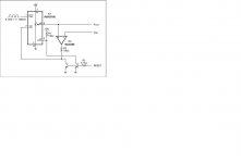
I came across this circuit a couple of years ago.
It's a droopless peak detector using a Maxum digipot and comparator.
With a little modification it could be converted to a tracking peak detector Using a window comparator and a proportional amplifier to detect a zero and control the up/dn pin
It's basically a digital integrator.
If the input signal is used to generate the clock the integration TC is adjusted with input frequency.
http://pdfserv.maximintegrated.com/en/an/AN1163.pdf
Attachments
Last edited:
If you use an R2R or log network you can get a lot more tuning out of the relays.
Drive the relays from a successive approximation register.
Cheers,
I prefer to have a minimum number of contacts. So I'll have to live with just 144 frequencies.
I would not worry about 600 Ohms..... a legacy relic of a bygone era. And opamp buffer will be fine for those 600 Ohms equipment. Or do as Krone-Hite does.... have an output directly off the osc and another output thru a buffer for low Z drive.
The K-H 4402B does 4 zeros and a 5 (with a few changes). Victor's is about half that. At 1KHz.
What does your design do at 10KHz?
Thx-RNMarsh
600 ohms is nice when you get into an output attenuator, which every audio generator really needs. The usual ladder attenuator produces a precision 600 ohms output impedance on each step. for the top (max out) step, you put in a 600 ohm series resistor. Now you have a precision 600 ohm output at all attenuator settings, and the generator is flat into any load in terms of what it is putting out at an impedance of 600 ohms. Note that the ladder does not actually load the output buffer with 600 ohms. For an example, see the output attenuator I use in my distortion analyzer's signal source.
Cheers,
Bob
I would not worry about 600 Ohms..... a legacy relic of a bygone era. And opamp buffer will be fine for those 600 Ohms equipment. Or do as Krone-Hite does.... have an output directly off the osc and another output thru a buffer for low Z drive.
The K-H 4402B does 4 zeros and a 5 (with a few changes). Victor's is about half that. At 1KHz.
What does your design do at 10KHz?
Thx-RNMarsh
I wouldn't say 600 ohms is a legacy relic. It's still a standard in recording studios, radio and TV stations. AP is still a 600 ohm output Z.
Its still a relic from the phone company days.
-RM
You can't do a proper transmission line with low Z. Your load would have to as low as the source Z. Direct from the output of an op the load would be so low there wouldn't be any signal at the end of the line. But we are spitting hairs here. Yes 600 ohms is a relic. It could have just as easily been 50 ohms. The 600 goes back to tube days. But there is no standard to replace it.
You asked for 10kHz. This is close.
Attachments
Its still a relic from the phone company days.
-RM
600 ohms is the characteristic impedance of open-wire telephone transmission lines. See this link for your amusement. From a 1930 Bell System Technical Journal. In true Bell Labs style, they even considered the effects of different insulators. The term "carrier" refers to frequency division multiplexing in long distance transmission systems.
http://www3.alcatel-lucent.com/bstj/vol09-1930/articles/bstj9-4-730.pdf
Cheers,
Bob
The practicle affect was to also help reduce cross-talk with standardized Z in/out/lines. Lines were/are not shielded.
I was Shift Chief at Frankfurt, Germany's largest carrier/microwave communications site (USA) for 2 years. [met my next to be German wife in Frankfurt]. During the night shift we did the QA tests on all the lines and fixed any that were out of spec. It was mostly F.D.Multiplex as you said. Got real good at trouble-shooting that stuff. Thats why I was at Ft Monmouth N.J. before the tour... learning the system for 8 hours a day in class for a year plus extra courses in group delay EQ techniques.
Better than ducking and dodging bullets in a rice field somewhere, I thought. Plus I already had college and was working at LLNL when drafted to go kill people in S.E Asia. Now I go back to Asia and get a condo there. Beautiful people in all ways. We could learn a lot from other cultures if we didnt blow them up.
-Richard
Last edited:
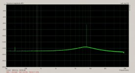
You can't do a proper transmission line with low Z. Your load would have to as low as the source Z. Direct from the output of an op the load would be so low there wouldn't be any signal at the end of the line. But we are spitting hairs here. Yes 600 ohms is a relic. It could have just as easily been 50 ohms. The 600 goes back to tube days. But there is no standard to replace it.
You asked for 10kHz. This is close.
Where? I dont see anything!
Hi Demian,
A tracking SV is what I would play with, A while back Samuel posted a 4th order SV oscillator. The design equation are available from Rane's website. It has a high sensitivity to matching elements of the tuning but that was with an un damped filter. There are four sections to tune.
It gives a nice 24dB LP. It provides quadrature outputs in all 4 phases. So a quadrature rectifier is probably the way to go with a mass of filtering or you can try the idea I suggested. If you want to go that route. Otherwise it's more sophisticated control like what Bob used in his analyzer.
What we need to know is how well the filter does with various tuning elements. For that a control system is not required, No point in developing one if the basic idea is flawed.
With that said maybe try some different filter types, SV, Wien etc. VCVA's like Sallen-key generate a lot of noise from the positive feedback. I wouldn't consider them. Passive LCR is a possibility but outside RF it's kind of a lost art.
Aside from your own suggestions I would try Mdac tuning. It's very promising and Mdacs can be paralleled to reduce noise and distortion. El beit a rather expensive route.
Cheers,
I will break this down into manageable segments since its easy to get lost in details. The first step is the low pass filter or integrator. The question is how much distortion would a filter add or remove? Several variables interact: opamp, level, circuit, loading and component values. Accepting that a VCVA will have a distortion problem (common mode issues) and noise (new to me) then I'll start with an integrator. I'll scale the impedance to 600 Ohms for now.
Key question- can a filter have less distortion at its output than the opamp in unity gain at the same level and loading?
Where? I dont see anything!
Well it was there. What happened to it?
Attachments

I will break this down into manageable segments since its easy to get lost in details. The first step is the low pass filter or integrator. The question is how much distortion would a filter add or remove? Several variables interact: opamp, level, circuit, loading and component values. Accepting that a VCVA will have a distortion problem (common mode issues) and noise (new to me) then I'll start with an integrator. I'll scale the impedance to 600 Ohms for now.
Key question- can a filter have less distortion at its output than the opamp in unity gain at the same level and loading?
That's a good question. Will a low pass active filter filter it's own distortion?
"Accepting that a VCVA will have a distortion problem (common mode issues) and noise"
I don't know about the distortion or common mode issues but they do raise a bit of noise.
It was one of the issues discussed with the post filters on the 339a.
Cheers,
The practicle affect was to also help reduce cross-talk with standardized Z in/out/lines. Lines were/are not shielded.
I was Shift Chief at Frankfurt, Germany's largest carrier/microwave communications site (USA) for 2 years. [met my next to be German wife in Frankfurt]. During the night shift we did the QA tests on all the lines and fixed any that were out of spec. It was mostly F.D.Multiplex as you said. Got real good at trouble-shooting that stuff. Thats why I was at Ft Monmouth N.J. before the tour... learning the system for 8 hours a day in class for a year plus extra courses in group delay EQ techniques.
Better than ducking and dodging bullets in a rice field somewhere, I thought. Plus I already had college and was working at LLNL when drafted to go kill people in S.E Asia. Now I go back to Asia and get a condo there. Beautiful people in all ways. We could learn a lot from other cultures if we didnt blow them up.
-Richard
"We could learn a lot from other cultures if we didn't blow them up. "
Not a great way of making friends is it.
- Home
- Design & Build
- Equipment & Tools
- Low-distortion Audio-range Oscillator