OK. SEnd me a paper on it. It did seem that it is right there at the jFET gate/osc interface. I havent measured the ripple there (45mv).
And with the S&H the ripple is effectively gone? And the results is....? Got any data/numbers, yet to put up here?
-RM
Hi Rick,
I think it would be best to have those numbers evaluated by a third party.
You by far have the most equipment. If you're interested and when the design is ready,
maybe I should put one together and send it down to you for testing. It would be just a test jig though. It will be some time before a complete design is ready. Control, buffer amp and attenuation is next.
Cheers,
I am ready any time you are. I'll leave the gear setup and ready for when you are.
-RM
Hi Rick,
I'm working on a second revision PCB. It takes over a month to get boards out of China from the time the order is placed. It will be a while. Samuel, IIRC, is working on his 3rd revision board. Changes may need to made to the next board. If the stuff is in your way then put it away for a while. Hopefully I'll have the main core of the oscillator done by this fall. This design business is a quick thing.
Cheers,
OK. I'll be puttering around trying ideas here and there or what-ever. Check out my bass drivers and digital cross-overs and get them going. But, mostly goofing off because its summer and beautiful. After this fall (winter), I'll be in Asia for awhile.... more goofing off in my newly completed condo there. It will need an Audio-Video system.
-RM
-RM
Last edited:
Apologies for not reading the thread but thought that some here might be interested in the oscillator architecture used in the paper linked:
http://cds.linear.com/docs/en/application-note/AN132f.pdf
----
Also:
I am not an expert but I did design a low-distortion audio sine oscillator, once (or, actually, dozens and dozens of times, for the one resulting oscillator circuit), for a test instrument. It produced sines with frequencies from 30 Hz to 22 kHz.
The main technique that I used, to lower the distortion, was a tracking low-pass post-filter. i.e. The filter automatically adjusted its cutoff frequency, relative to the output sine's fundamental frequency, so that the harmonics would be filtered more than the fundamental.
The automatic cutoff-frequency adjustment scheme that I finally hit on was dead-easy. I was using several buffered stages of simple RC low-pass filters, each with a current-controlled resistance made with a VTL5C2 Vactrol (an LED and a CdS photocell encapsulated together in a light-tight package), to avoid the problems of jfets. The input to the post-filter was at approximately the same amplitude for all audio frequencies. I simply used an ALC (automatic level control) feedback loop to control the current through the LEDs, to vary the RCs' cutoff frequency until the filtering brought the post-filter's output amplitude down to a pre-determined level, which was somewhat lower than the filter input's level. That had the effect of always lowering the cutoff frequency until it was in the desired position, relative to the fundamental. (I used a fixed voltage for the ALC's target level, since the input amplitude was relatively constant versus frequency. But for an input level that varied with frequency, the target level could easily be derived from the input level.)
The VTL5C2s were pretty easy to use. Their resistance varied from well over 1 megOhm to about 40 Ohms for LED currents of 0 mA to 40 mA. Their resistance vs LED current relation was not linear (more like logarithmic). But that's one of the beauties of feedback control loops, especially when all you really care about is the end state.
Cheers,
Tom
Last edited:
A tracking low pass was suggested awhile back as well as a tracking notch filter to remove 2H (or any other Harmonic). But, its good to know someone who has actually designed such circuits.
Is your circuit the same or different from the AN132f article? How could you further lower the THD of the oscillator.... 1ppm or less?
Thx-RNMarsh
Is your circuit the same or different from the AN132f article? How could you further lower the THD of the oscillator.... 1ppm or less?
Thx-RNMarsh

Apologies for not reading the thread but thought that some here might be interested in the oscillator architecture used in the paper linked:
http://cds.linear.com/docs/en/application-note/AN132f.pdf
----
Also:
I am not an expert but I did design a low-distortion audio sine oscillator, once (or, actually, dozens and dozens of times, for the one resulting oscillator circuit), for a test instrument. It produced sines with frequencies from 30 Hz to 22 kHz.
The main technique that I used, to lower the distortion, was a tracking low-pass post-filter. i.e. The filter automatically adjusted its cutoff frequency, relative to the output sine's fundamental frequency, so that the harmonics would be filtered more than the fundamental.
The automatic cutoff-frequency adjustment scheme that I finally hit on was dead-easy. I was using several buffered stages of simple RC low-pass filters, each with a current-controlled resistance made with a VTL5C2 Vactrol (an LED and a CdS photocell encapsulated together in a light-tight package), to avoid the problems of jfets. The input to the post-filter was at approximately the same amplitude for all audio frequencies. I simply used an ALC (automatic level control) feedback loop to control the current through the LEDs, to vary the RCs' cutoff frequency until the filtering brought the post-filter's output amplitude down to a pre-determined level, which was somewhat lower than the filter input's level. That had the effect of always lowering the cutoff frequency until it was in the desired position, relative to the fundamental. (I used a fixed voltage for the ALC's target level, since the input amplitude was relatively constant versus frequency. But for an input level that varied with frequency, the target level could easily be derived from the input level.)
The VTL5C2s were pretty easy to use. Their resistance varied from well over 1 megOhm to about 40 Ohms for LED currents of 0 mA to 40 mA. Their resistance vs LED current relation was not linear (more like logarithmic). But that's one of the beauties of feedback control loops, especially when all you really care about is the end state.
Cheers,
Tom
Neat idea!
I had given some thought to using a second SVF configured as a 2nd order LPF after the SVO, using the same tuning approach (doubling all of the tuning stuff). This looks simpler.
Cheers,
Bob
Neat idea!
I had given some thought to using a second SVF configured as a 2nd order LPF after the SVO, using the same tuning approach (doubling all of the tuning stuff). This looks simpler.
Cheers,
Bob
Don't forget the level control goes before the filter! If you do it as a nice PC card design with relay switching of the tuning elements you can also look at paralleling filters to reduce noise.
The biggest trade off that I am aware of is that to get low noise you want low impedance and that requires larger capacitors that are slightly more prone to vibration induced noise.
In my simulations SVF works better than Wein, when I build them Wein works better.
")
Do let me know what you do. I think my next project is a method to measure the distortion and noise of oscillators. But first I have to finish my power supply novel.
ES
Don't forget the level control goes before the filter! If you do it as a nice PC card design with relay switching of the tuning elements you can also look at paralleling filters to reduce noise.
The biggest trade off that I am aware of is that to get low noise you want low impedance and that requires larger capacitors that are slightly more prone to vibration induced noise.
In my simulations SVF works better than Wein, when I build them Wein works better.
Do let me know what you do. I think my next project is a method to measure the distortion and noise of oscillators. But first I have to finish my power supply novel.
ES
Yes, I had also thought of the agc, recognizing that any frequency setting error in the post filter would cause amplitude error. The solution I came up with was to put a second agc detector at the output of the SVF LPF and route the control loop feedback to the (normally fixed) amplitude control level voltage of the agc loop of the oscillator. Sort of nested agc loops.
Note that the required authority and range of this second agc loop would only need to be quite small, as it is just an amplitude trim.
The nice thing about this is that you can heavily filter the second loop without incurring the same stability problems because you are not trying to agc an oscillator (which acts like a higher-order system from the point of view of the agc loop).
Cheers,
Bob
A tracking low pass was suggested awhile back as well as a tracking notch filter to remove 2H (or any other Harmonic). But, its good to know someone who has actually designed such circuits.
Is your circuit the same or different from the AN132f article? How could you further lower the THD of the oscillator.... 1ppm or less?
Thx-RNMarsh
My circuit was nothing special, really, and was not similar to the one in AN132f. I did not have a requirement for extremely-low distortion. And the initial sine came from a leveled triangle-to-sine converter (made with two LM394 and three op amps). It had about 0.3% THD.
With three stages of simple buffered first-order RC low-pass filtering, the THD went from about 0.3% to about 0.01% for a 60 Hz sine, which was good-enough for that application. I think that I probably would have used more filter stages but I was out of space on the PCB.
The filter's ALC feedback loop used an ideal peak detector, some low-pass filtering, and a differential integrator (with a parallel "speed-up" input path for large differentials), with a reference voltage on one input.
The output of the integrator went through a series current-limiting resistor and then through all of the VTL5C2s' LEDs, in series, and then to the negative supply rail. Looking at the schematic I see that I used 0.01uF film capacitors, for the RC filters. All of the op amps were OP275.
The biggest trade off that I am aware of is that to get low noise you want low impedance and that requires larger capacitors that are slightly more prone to vibration induced noise.
ES
The choice of small value caps and varying the range of R's is a basic stumbling block to better performance. There are brands/makes/models of caps which are not microphonic/vibration prone in the slightest. I'll give sources when we get there. So let this not be an issue.
Thx-RNMarsh
Actually this could be done with a very simple control circuit. Don't need the usual osc typ AGC. A fixed integrator, a couple of comparators and analog switches.
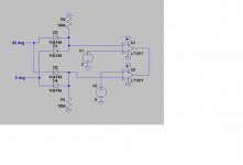
Here is a quadrature level detector I put together for a speedup circuit for my SVO.
This detects the RMS level of quadrature sines.
Two of these could be used. One to detect a low level and the other to detect a high level.
The LT1017 swings rail to rail. The insertion of a diode at the output and resistor shunt to ground limits the output to positive or negative depending on the direction of the diode. The LT1017 has it's output internally loaded with a 100uA current source so outputs from two can be directly tied together.
Cheers,
Attachments
Last edited:
Yes, I had also thought of the agc, recognizing that any frequency setting error in the post filter would cause amplitude error. The solution I came up with was to put a second agc detector at the output of the SVF LPF and route the control loop feedback to the (normally fixed) amplitude control level voltage of the agc loop of the oscillator. Sort of nested agc loops.
Note that the required authority and range of this second agc loop would only need to be quite small, as it is just an amplitude trim.
The nice thing about this is that you can heavily filter the second loop without incurring the same stability problems because you are not trying to agc an oscillator (which acts like a higher-order system from the point of view of the agc loop).
Cheers,
Bob
I think the real issue will be the Q of the SVF. It looks to me like that will have a large effect on noise performance. In the filters I have played with Q is set by increased stage gain, thus more noise and less bandwidth, Where the optimum is should be an interesting question.
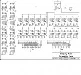
Attached is my idea of a master oscillator. The filter section would use a dual op amp filter otherwise pretty much the same.
ES
Attachments
Last edited:
Will you test this [using two] and put it in your new osc design?
-RM
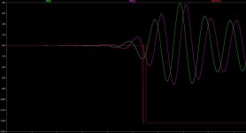
In my oscillator it controls a start up / speed up circuit which switches a bypass resistor around the multiplier to kick the gain up momentarily. Once the level is near set point the resistor is switched out and the AGC takes authority. The sampler won't start at power up until it has signal because the timing is generated from the signal. If for any reason the oscillator should stop the speed up circuit will restart it. But there is no reason it should stop once started.
A tracking filter doesn't need a fast AGC. The level detector circuit is just a suggestion for a simple means of tuning a tracking filter. A tracking filter was never in the plan but I might look into it later on. The idea is intriguing. I'm not sure how effective an active filter would be since the filter adds noise and distortion of it's own. As a means of cleaning up a cheap stock oscillator it might be just the thing but it may not have any benefit for an ultra low distortion oscillator.
A control system that does it's thing and then shuts itself off would less intrusive on the filter than PI AGC.
Cheers,
I think the real issue will be the Q of the SVF. It looks to me like that will have a large effect on noise performance. In the filters I have played with Q is set by increased stage gain, thus more noise and less bandwidth, Where the optimum is should be an interesting question.
Attached is my idea of a master oscillator. The filter section would use a dual op amp filter otherwise pretty much the same.
ES
If you use an R2R or log network you can get a lot more tuning out of the relays.
Drive the relays from a successive approximation register.
Cheers,
An important question is if its possible for a filter (inegrator) to contribute less ditortion than it removes, further- what is the optimum solution for the filter.
If a filter can be used to significantly improve an ultra low distortion oscillator then the cleanest, quickest oscillator solution might be a DAC (driven appropriately) followed by one or more of these filters tuned appropriately. The DAC will have much less phase noise and level instabilities than any other type. Harmonics all below -110 dB is very ppossible today from several vendors. Followed by the filter would reduce the remaining harmonics (and any other noises) as per the filter. A well designed passive filter could get really exceptional performance if the losses and inductor distortions are dealt with.
For tuning I don't see where using the jfet switched digital pots (JRC or Maxim) would be a limitation in a tuning network. You get two that track very closely (better than 1%) and some variants can be controlled via contacts.
An important question is if its possible for a filter (inegrator) to contribute less ditortion than it removes, further- what is the optimum solution for the filter.
If a filter can be used to significantly improve an ultra low distortion oscillator then the cleanest, quickest oscillator solution might be a DAC (driven appropriately) followed by one or more of these filters tuned appropriately. The DAC will have much less phase noise and level instabilities than any other type. Harmonics all below -110 dB is very ppossible today from several vendors. Followed by the filter would reduce the remaining harmonics (and any other noises) as per the filter. A well designed passive filter could get really exceptional performance if the losses and inductor distortions are dealt with.
For tuning I don't see where using the jfet switched digital pots (JRC or Maxim) would be a limitation in a tuning network. You get two that track very closely (better than 1%) and some variants can be controlled via contacts.
Hi Demian,
To answer these questions one of us has to build these circuits and test them. I'm kind of busy with my current project.
Cheers,
I think the real issue will be the Q of the SVF. It looks to me like that will have a large effect on noise performance. In the filters I have played with Q is set by increased stage gain, thus more noise and less bandwidth, Where the optimum is should be an interesting question.
Attached is my idea of a master oscillator. The filter section would use a dual op amp filter otherwise pretty much the same.
ES
Yes, there is probably an optimum tradeoff between filter Q and added noise. Higher Q, such as with an LPF that deliberately has a peak at the fundamental frequency, may also place greater demands on tuning tracking between the SVO and SVF, and/or the authority of the secondary agc.
One advantage, distortion-wise, that the clean-up filter has over the oscillator is that the cleanup filter does not involve an agc device, like a JFET, to be a source of distortion. Similarly, any agc ripple distortion will be smaller in the clean-up filter because more filtering can be used in its agc loop while maintaining agc loop stability.
The noise issue is always an important one, even in the SVO without a clean-up filter. For example, the distortion of the agc element can be reduced arbitrarily by reducing the voltage on it, but at the expense of increased noise for a given agc authority.
Cheers,
Bob
- Home
- Design & Build
- Equipment & Tools
- Low-distortion Audio-range Oscillator