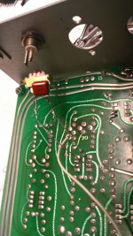
First, how I added injection locking to the KH4400. Its a junk box Radio Shack transformer (1:1) and two 100K resistors and a cap. I used a transformer to get ground isolation. It did not really work. I need to find a shielded transformer.
Then the QA400 during measurements runs the generator in bursts. This does not work well with injection locking.
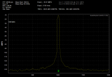
Fortunately the Boonton 1120 can be set very precisely (6 digits) and is locked to a TXCO. (I get value from the toy. . . )
I locked the KH4400 to the Boonton set to the frequency of the QA400 internal generator. You can see how the skirts narrow when the generator is locked. You will also see the third harmonic increase when locked.
Then the QA400 during measurements runs the generator in bursts. This does not work well with injection locking.
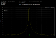
Fortunately the Boonton 1120 can be set very precisely (6 digits) and is locked to a TXCO. (I get value from the toy. . . )
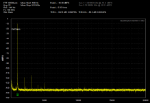
I locked the KH4400 to the Boonton set to the frequency of the QA400 internal generator. You can see how the skirts narrow when the generator is locked. You will also see the third harmonic increase when locked.
Attachments
Dick, the comparison was aluminum with fins, anodization, and all the other good stuff. the copper was just a lump. I keep pointing out there is nothing to learn unless ALL the factors are covered.
Scott, one thing to check is whether your buddy actually allowed for enough time to reach equilibrium. Until that point, his block of copper may well look better, but possibly after equilibrium, the alu-with-fins might do better.
The copper may rise slower in temp, but end up at a higher final temp.
jan
Last edited:
Scott
The other issues are that the e of tarnished copper is quite high. As mentioned copper conducts heat much better so all of the surface area will be at the same t. And of course the method used to measure the t. A probe with putty is accurate an ir sensor can give silly readings. That brings up the issue of the anodizing. Black is the color you see. There are different methods to get to black. The cheapest way is with a dye. Cheaper dyes are not as black at ir as the better ones from sources such as Sandoz.
I thought the distortion reduction in injection locking were clear. If you do a high level of 10% that is 20 db. Even a square wave has only 1/3 sin (3x) or another -10 ish. Add the minimum two pole filtering of the tuning elements for another 18 on the 3rd.
Now 10% is a high injection level. But you are starting with a clean sine wave. In actual practice they of course don't exist. Also for most folks locking at 1% injection from the output of a digital frequency divider has low enough distortion, there is no reason to go any cleaner.
Now using a D-A with smarts behind it opens entirely new methods of not just locking it but also opens up all the other control issues. Not just loop gain and matching harmonic cancelation, but also some neat sampling based cancelation or correction techniques.
ES
Scott
The other issues are that the e of tarnished copper is quite high. As mentioned copper conducts heat much better so all of the surface area will be at the same t. And of course the method used to measure the t. A probe with putty is accurate an ir sensor can give silly readings. That brings up the issue of the anodizing. Black is the color you see. There are different methods to get to black. The cheapest way is with a dye. Cheaper dyes are not as black at ir as the better ones from sources such as Sandoz.
I thought the distortion reduction in injection locking were clear. If you do a high level of 10% that is 20 db. Even a square wave has only 1/3 sin (3x) or another -10 ish. Add the minimum two pole filtering of the tuning elements for another 18 on the 3rd.
Now 10% is a high injection level. But you are starting with a clean sine wave. In actual practice they of course don't exist. Also for most folks locking at 1% injection from the output of a digital frequency divider has low enough distortion, there is no reason to go any cleaner.
Now using a D-A with smarts behind it opens entirely new methods of not just locking it but also opens up all the other control issues. Not just loop gain and matching harmonic cancelation, but also some neat sampling based cancelation or correction techniques.
ES
Ed I thought you said to avoid a pure sine wave? That's what made no sense. It turns out this system seems to act like an ultra high Q amplifier which is perfect. This will reject the injectors harmonics by a huge amount. I think you misunderstand I am pulling the frequency by 10% the amplitude is tiny.
Also I have to apologize a little on the heatsink stuff. I have been fighting this for years. The JEDEC specs for ThetaJA are very pessimistic because the don't include things that would apper in a normal application like conduction out the leads. Parts are to be measured soldered to small dots on tiny boards.
Does it make sense to thermally isolate a heatsink and mount it upside down to defeat natural convection to prove the point that radiation can be up to 20% of the loss? (number from IBM) Bolted to the chassis and free and clear to encourage natural convection we are down to a few percent at best difference. BTW turning off radiation all the way in that program will give a wrong answer anyway, raw aluminum extrusion is .2-.3 emissivity.
Last edited:
FYI -- View attachment 342057
So there you are. Clear now? Good.
[Physicsforums.com/archive/index.php/t-131758.html]

That's why copper bottoms are put on cooking pots. Nothing new here.
Scott,
I thought you misread that. Using a simulation with a clean sine wave is misleading because that is not how it was normally done.
I though you were injecting 10% because of component tolerances. 1% is typical. A pull range of 10% is wide, normal is +3/-2 or so. I have done most of this with Wein bridges.
As you know the e part of the heatsink depends on operating temperature. For an exposed heatsink 45C is often the limit to prevent injury. Inside a case you might see 80C with modern power transistors. Allowable die temperatures are 50C higher than when I started designing stuff. So the e ratio really depends on how hot you can take it. BTY 10% is what I would consider starting to be significant.
On a cost basis it is about $.03 per square inch for quality anodizing in small quantities. A .1" x 1" x 1" piece of aluminum costs just about the same. Makes the economics interesting.
ES
Scott, one thing to check is whether your buddy actually allowed for enough time to reach equilibrium. Until that point, his block of copper may well look better, but possibly after equilibrium, the alu-with-fins might do better.
The copper may rise slower in temp, but end up at a higher final temp.
jan
That was the first suggestion from the gathered elites.
")
Demian
Ever try two transformers in series? (Load R between them.)
ES
Good idea. I'll need to check the junk box. I can ground the intermediate connections to reduce the noise coupling.
That was the first suggestion from the gathered elites.
That does make me feel good!
jan
There are several heat sink mfr which offer combinations of alum and copper in their products. Some blend copper into the Alum to make a composite metal. Other mold Alum over copper. for example, plate copper embedded nearest the device (Xistor) and Alum fins further away.... all in one packaged heat-sink. The best of both worlds.
Thx-RNMarsh
Thx-RNMarsh
Last edited:
The "close in phase noise" is normally related to the amplifier noise and the Q of the frequency network. Injection locking brings the noise of the locking source to the oscillator and that can be better. Typically the close in noise is from the external source and the further out (and harmonics) are from the local generator.
Its pretty impressive how good the tuning of the Boonton is since its done by a micro and reciprocal counter and a dac into a multiplier. The tuning of the loop must be really good. A divided down crystal should be better but I have had hum sidebands limiting my efforts so far. I need to build a dedicated circuit for this.
Its pretty impressive how good the tuning of the Boonton is since its done by a micro and reciprocal counter and a dac into a multiplier. The tuning of the loop must be really good. A divided down crystal should be better but I have had hum sidebands limiting my efforts so far. I need to build a dedicated circuit for this.
perhaps when I got the noise down the thd was lower also in part due to reduced jitter... nice combination to have.
I seem to recall or imagine that as low as 100Khz Xtlas exist - used to.
-RM
PS -- yes and there are some on eBay at this time (att). Even a 100Khz xtal with oven in octal base for $25.
If there is a choice - best to get used xtals as they are more stable.
I seem to recall or imagine that as low as 100Khz Xtlas exist - used to.
-RM
PS -- yes and there are some on eBay at this time (att). Even a 100Khz xtal with oven in octal base for $25.
If there is a choice - best to get used xtals as they are more stable.
Last edited:
I just want to be the first to say this. How about punt the oscillator all together? Put a small pot into the Wien bridge circuit and use it like a "tickler" in a super-regen making a super high Q amplifier. 40-50 dB rejection on a good sound card sine wave is pretty good. Simulation looks fine, as Samuel points out the noise issues are always there since you have an essentially "infinite" noise gain at the oscillation frequency and the skirts seem to vary only a little.
I just want to be the first to say this. How about punt the oscillator all together? Put a small pot into the Wien bridge circuit and use it like a "tickler" in a super-regen making a super high Q amplifier. 40-50 dB rejection on a good sound card sine wave is pretty good. Simulation looks fine, as Samuel points out the noise issues are always there since you have an essentially "infinite" noise gain at the oscillation frequency and the skirts seem to vary only a little.
I mentioned I did this many posts back! You also want to parallel the just below oscillators to lower the noise.
When I started getting serious mid 70's I made my low distortion oscillators and analyzer. I used a biquad filter made of socketed IC's for the distortion analyzer. I then ran through my stock of then state of the art 5534's and found the NEC version had the lowest noise. By using 18 & 20 khz test signals I was able to measure to 10 PPB. (ish maybe 20)
I found I could make circuits with distortions of under 50 PPB until you actually connected them to a load then they shot up to 1000's PPB.
One interesting tidbit was I originally thought that if an amplifier was set up as inverting you would get lower distortion. Turns out the best I could get inverting was 300 PPB.
Even though I had built a DFT analyzer using the Reticon chip, that test system was my mainstay until around 95. Then I went to a sound card and PC. Now that my AP isn't cutting it I have been doing work arounds and looking for something new.
When I started getting serious mid 70's I made my low distortion oscillators and analyzer. I used a biquad filter made of socketed IC's for the distortion analyzer. I then ran through my stock of then state of the art 5534's and found the NEC version had the lowest noise. By using 18 & 20 khz test signals I was able to measure to 10 PPB. (ish maybe 20)
.
There is no 5534 that supports even ppm THD. Separate oscillators and IMD is a very different problem, PSRR and crosstalk could be factors there. These days the noise is not an issue, why shoot yourself in the foot use FFT's get the noise BW down to an insignificant number. Doubling the FFT length is the same as having two oscillators, the bits are way less pain.
There is no 5534 that supports even ppm THD. Separate oscillators and IMD is a very different problem, PSRR and crosstalk could be factors there. These days the noise is not an issue, why shoot yourself in the foot use FFT's get the noise BW down to an insignificant number. Doubling the FFT length is the same as having two oscillators, the bits are way less pain.
That is why I said oscillators and have brought up using IMD measurements instead of THD. IMD works much better and is easier to isolate using analog techniques.
The problem with FFT is A/D limits. If you dither and average you certainly can see distortion a bit lower, but I really don't care about most distortion type of measurements once they go below the other issues.
Noise is more of an issue in design limits from the sandbox I play in.
For example as mentioned I have been letting my guys play with mic preamps. My issue is do I want to actually design and build a new one. If I do then from what I have learned it will be two times two stages with an output buffer. There would be a transformer input split into first paralleled amps noninverting and then single amp (x2) inverted signal paths as Langevin did in the 40's. The gain trim would affect all four stages equally. The output would have a follower buffer inside the second stage global feedback loop.
That addresses EMI, noise, inverted distortion products being equal would series cancel, some would balance cancel and loading issues would be significantly reduced.
Now using a chip like the AD797 with a step up transformer would give me a noise figure better than the real impedance of most dynamic microphones. But I have diverted too much from the topic...
Whether one chooses FFT or other means to determine thd/harmonics.... or some other application for the purest of pure oscillator -- it is clear thd +n is the metric to work with. Get them both down. It doesnt matter that there is noise at the osc freq, either. Or noise gain at the osc freq... except in that it creates jitter induced freqs. But that can be dealt with after the osc itself is optimized. High Q helps, too. So how to combine all into one topology.
Can we get a block diagram from all (Scott, Samuel and Simon) on proposals? Start to fill in some blanks and blocks with circuits... both can be done and compared if they are very different in approach.
Thx-RNmarsh
I like the concept of no osc or one which can include cancellation as opposed to more and more linear -only.
- Home
- Design & Build
- Equipment & Tools
- Low-distortion Audio-range Oscillator