can we make a copy of your ADC design to use? Do you have any data on its performance?
Thx-RNMarsh
I can dig out some test results. The design itself was made at work, so I don't think I can share it. Or at least not all of it. On the other hand, it is not very special. Just a fairly good op-amp buffer, the ADC, a clean clock and a sensible PCB layout.
Are you going to make a pcb layout for it to be built (DIY) or make some pcb's for us to buy?
Hi Rick,
There is still a lot of development to do yet.
The spectra you've seen is with fixed tuning resistors and jumpers for range selection.
As long as the tuning scheme I have planned doesn't mess thing up the things will move along faster. There is also skepticism on the measurement method's accuracy and everything needs to be verified by second source testers first before offering boards.
Yes boards and or kits will be available.
The scope probe was in a sensitive place when doing the 12kHz measurement.
The disto is quite a bit lower. Add 3dB to second H for TT atten.
Attachments
So lets lower the source R to the practical smallest amount, then.
That's only the first half. You also need a phase shifter that does not have
a lot of loss, because the sustaining amplifier will have to make up for it,
and doing that it will amplify its own noise, too.
Loss and gain in the loop add to 0 dB in the stationary case.
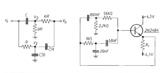
Thinking about that I remembered James G. Holbrook's textbook on
Laplace Transforms, where he presented a RC network that features
voltage _GAIN_ (just a few %) at 0 deg. phase shift, so it should
oscillate with a follower. He has US patent 2769088 on it. Definitely EOL.
I just entered it into LTspice and while it seems to work, the phase slope
at 0° is _very_ flat, so the phase noise is probably really bad. I have not
made up my mind if this hurts this application.
The positive gain region with the components given is about 50 to 500 Hz.
He also has a RC network with 21% gain, but today for me, it's late enough.
regards, Gerhard
Attachments
Last edited:
where he presented a RC network that features
voltage _GAIN_ (just a few %) at 0 deg. phase shift, so it should
oscillate with a follower.
When I was very young I tried this one by Murphy (the picture is from an old italian magazine) - it worked
")
Spice says that with shown values voltage gain is about 1.55 dB @ ~1.6 kHz (and 0 deg phase shift).
Ciao,
L.
Attachments
Would more gain from a compound arrangment help here? two opamps as one. Would extend the] freq range of operation (?)
I'm not sure if I understand the question. There are GHz opamps nowadays
that feature a few nV/sqrt Hz, so frequency range should not be important.
My point is that if you drown a signal in a RCRCRCRC phase shifter to get
180° shift for an inverting CE stage, every 45° costs 3 dB in amplitude
(minimum phase network, ignoring previous RC stage loading). When you
fight for 3 dB noise that's much.
For a phase shift oscillator (RCRCRCRC from C to B) a gain stage after RCRC
would probably pay for itself in terms of noise.
getting really sleepy now
Gerhardpics of the Holbrook stuff:
Attachments
Last edited:
I'm not sure if I understand the question. There are GHz opamps nowadays
that feature a few nV/sqrt Hz, so frequency range should not be important.
My point is that if you drown a signal in a RCRCRCRC phase shifter to get
180° shift for an inverting CE stage, every 45° costs 3 dB in amplitude
(minimum phase network, ignoring previous RC stage loading). When you
fight for 3 dB noise that's much.
For a phase shift oscillator (RCRCRCRC from C to B) a gain stage after RCRC
would probably pay for itself in terms of noise.
getting really sleepy now
pics of the Holbrook stuff:
I think he means a composite amplifier to get the gain up.
The HP, KH and others have had their noise drop 20+ dB with opamp changes.
As Scott points out, this is very unlikely unless the original designers did a bad job, and much more likely a measurement error or misinterpretation of measurement results. If you want us to believe the results, you'd need to show before-after results, with the exact measurement procedure (analyzer type, parameter settings etc.) unambiguously documented.
Why is this so hard to do? Just make an osc with best performance--with best opamp and get as low noise and THD as possible.
If, after 214 pages in this thread and countless secondary resources listed, it is indeed not clear what the difficulties involved are, I can only repeat that looking at the individual distortion and noise sources in isolation is the only way to really understand the performance limitations of oscillators. Everything else must remain, to some degree, building a house of cards. Divide and conquer--already the old Romans knew that.
There are GHz opamps nowadays that feature a few nV/sqrt Hz, so frequency range should not be important.
All of these run at most on +-5 V rails, have tons of 1/f in the audio frequency range and high distortion. So unfortunately completely useless for what we're doing here.
More gain and less noise with RC split between the two opamps.
Composite opamps are surely a very powerful approach to get very low distortion, and a wise consideration for a state-of-the-art oscillator. I'm not quite sure though why you think it would reduce noise.
I can however also indicate that this approach is not free from unexpected issues, e.g. some configurations are prone to latching up a SVF topology during power-up or clipping.
Samuel
As Scott points out, this is very unlikely unless the original designers did a bad job, and much more likely a measurement error or misinterpretation of measurement results. If you want us to believe the results, you'd need to show before-after results, with the exact measurement procedure (analyzer type, parameter settings etc.) unambiguously documented.
I have shown the test setup.... it doesnt matter to me that the noise floor levels are relative or absolute. Absolute seems to be on some others minds.... With the same equipment set up and same scales, the noise drops compared to original opamp used. I dont care about absolute all that much at this time..... I am measuring thru the monitor port of an analyzer and not from the osc directly... so Obviously, it isnt a measure of the osc noise alone/itself. Its the osc noise plus the analyzer noise and what else. It was shown clearly what I am doing. For the DIY'er, lower is just lower by X dB. Same with the THD.... lower is lower by X amount. Except in the THD case, it is accurately measured to the instruments limits of uncertainty/tolerance/accuracy/precision. -RNM
Composite opamps are surely a very powerful approach to get very low distortion, and a wise consideration for a state-of-the-art oscillator. I'm not quite sure though why you think it would reduce noise. Dont know .... a secondary issue.... just speculating that it might. Want lower thd. So far the noise has fallen as a fortuitous benifit of the process applied. -RNM
I can however also indicate that this approach is not free from unexpected issues, e.g. some configurations are prone to latching up a SVF topology during power-up or clipping.
Samuel
This is the only part relavent to what I am concerned with. I am also not interested in reinventing the wheel. If you and others can do better then lets do it here and now. I am not going to do it myself nor by myself. The alternatives are to buy commercially available at high cost or DIY. DIY has taken several paths - one is to modify existing older oscillators to see if they can have improved performance.... argue what you will about the tech results but they have been improved in thd and noise. Started with the HP339A which Davada led many of the upgrades/advances on.
Thx-RNMarsh
Last edited:
This is the only part relavent to what I am concerned with. I am also not interested in reinventing the wheel. If you and others can do better then lets do it here and now. I am not going to do it myself nor by myself. The alternatives are to buy commercially available at high cost or DIY. DIY has taken several paths - one is to modify existing older oscillators to see if they can have improved performance.... argue what you will about the tech results but they have been improved in thd and noise. Started with the HP339A which Davada led many of the upgrades/advances on.
Thx-RNMarsh
"I am also not interested in reinventing the wheel"
Maybe a Nobel price?
"If you and others can do better then lets do it here and now."
Why?
As I told you in another thread it is possible to do it better, but in my opinion that would be a dedicated discrete design (DDD) not swapping OPAMP's.
BTW: Sorry for being late into this discussion, I have not read the whole thread, only the last few pages, but it is an interesting issue.
Stein
Well, this is what I and other's want to make.... I had inquired about the ShibaSoku generator and at 9.2K USD I figured there must be some others around who have looked into this in depth and can move the needle forward from where the tech stopped, commercially, decades ago.
This forum is about doing that and I am willing to pass the batton to others who would take up the challenging project and are much more knowledgeable for a DIY project. A descrete circuit osc would be another variation to attempt. Are you in?
BTW- The Panasonic 7723 uses a discrete circuit in its osc but doesnt do better than the others with opamps in regards to THD.
Thx-RNMarsh
Last edited:
@RNMarsh
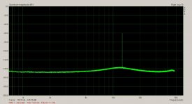
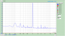
I promised you a measurement result made with my CS5381 based ADC. In this case I have used a Stanford Research DS360 as generator. The level was 1.83V balanced, which is around 1 dB below max.
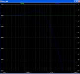
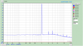
The 50Hz hum and harmonics are due to the generator/mains noise. A similar test with my own DAC does not have this problem. See the second picture. The distortion level is higher though.
I promised you a measurement result made with my CS5381 based ADC. In this case I have used a Stanford Research DS360 as generator. The level was 1.83V balanced, which is around 1 dB below max.
The 50Hz hum and harmonics are due to the generator/mains noise. A similar test with my own DAC does not have this problem. See the second picture. The distortion level is higher though.
Attachments
For those who dont like to read a lot --- we recap every so often:
The 339A is a thd+N meter. The osc and analyzer spec is .0018% or better. That is a tick below the 0.2 mark on the 0-1 scale (-80dB =1).
After opamp and parts changes and upgrades, the thd+n is near the 0 mark -- well below -100dB. This is THD+N.
Using the 339A monitor output shows the two dominant harmonics at -106db and -110dB for 3H. The top is -100dB and 10dB/div. and measured with shibasoku 725D analyzer ported to an HP 3580A Spectrum Analyzer to measure individual harmonic and noise levels. This is a compromise tuning for a wide range of freqs; For minimum thd+n at only one freq, it can be much lower:


At this point in time we started using an FFT (Davada's QA400) on the monitor port instead. Then I got the ShibaSoku analyzer which can do both what the 339A and an FFT does. But they are rare and expensive. I continued on with just various other oscillator upgrades and davada and others worked on the FFT. Notch filters exist and are shown in other forums. I built one of the notch filters and am working to get an FFT that works with my cpu system without problems. A clean source and portable test system is highly desirable over my bench equipment/system.
Thx-RNMarsh
The 339A is a thd+N meter. The osc and analyzer spec is .0018% or better. That is a tick below the 0.2 mark on the 0-1 scale (-80dB =1).
After opamp and parts changes and upgrades, the thd+n is near the 0 mark -- well below -100dB. This is THD+N.
Using the 339A monitor output shows the two dominant harmonics at -106db and -110dB for 3H. The top is -100dB and 10dB/div. and measured with shibasoku 725D analyzer ported to an HP 3580A Spectrum Analyzer to measure individual harmonic and noise levels. This is a compromise tuning for a wide range of freqs; For minimum thd+n at only one freq, it can be much lower:
At this point in time we started using an FFT (Davada's QA400) on the monitor port instead. Then I got the ShibaSoku analyzer which can do both what the 339A and an FFT does. But they are rare and expensive. I continued on with just various other oscillator upgrades and davada and others worked on the FFT. Notch filters exist and are shown in other forums. I built one of the notch filters and am working to get an FFT that works with my cpu system without problems. A clean source and portable test system is highly desirable over my bench equipment/system.
Thx-RNMarsh
Last edited:
One of the other oscillators to be tuned/tweeked was a Krone-Hite 4400 and a KH-4402B. Not much improvement occured with the 4400. but the 4402B responded quit well to the kinds of changes done with the HP339A.
The comparison is with Vicktors precision osc (eBay). The THD is about the same (1KHz) now (-140). With such low THD residuals, noise dominates the measurement for THD+N. There is only a few dB difference between THD+N and THD. Sometimes the difference is only 1dB when the filters are on for min BW. Other filtering which measures wider BW of harmonics and noise goes to 6 or even +10dB on some osc models. Here the shown difference is 4dB for the shown settings. There is no standard for such osc testing (I also can do "A" weighted thd+n) testing. Under the best conditions i can get close to -130dB THD+N. Individual harmonics are much lower. Again, the exact level depends on tuning for one freq or tuning for compromise. I choose compromise and tune for 100Hz to 10KHz balance with 2H and 3H.


Thx-RNMarsh
The comparison is with Vicktors precision osc (eBay). The THD is about the same (1KHz) now (-140). With such low THD residuals, noise dominates the measurement for THD+N. There is only a few dB difference between THD+N and THD. Sometimes the difference is only 1dB when the filters are on for min BW. Other filtering which measures wider BW of harmonics and noise goes to 6 or even +10dB on some osc models. Here the shown difference is 4dB for the shown settings. There is no standard for such osc testing (I also can do "A" weighted thd+n) testing. Under the best conditions i can get close to -130dB THD+N. Individual harmonics are much lower. Again, the exact level depends on tuning for one freq or tuning for compromise. I choose compromise and tune for 100Hz to 10KHz balance with 2H and 3H.
Thx-RNMarsh
Last edited:
injection locking
I've been playing with this in simulation since I think Mr Brisbois was operating in empirical mode. It is very interesting almost in a way like a super-regenerative amplifier. I don't know exactly what is going on but it is very intriguing, I get some shockingly low THD numbers.
Thought experiment; if you could get exact frequency lock you should be able to generate an exact quadrature signal, in which case the sin^2 + cos^2 amplitude detector circuit could be made to work perfectly with no ripple.
Does it look hard to keep right on the 'spot' for null distortion over a wide freq range? How hard will it be to stay locked at low freqs and very low freqs?
Are you ready to show a sketch of the circuit/topology at this time?
And, if you could do it, would ADevices do it in an IC package?
-RNm
Are you ready to show a sketch of the circuit/topology at this time?
And, if you could do it, would ADevices do it in an IC package?
-RNm
Last edited:
I've been playing with this in simulation since I think Mr Brisbois was operating in empirical mode. It is very interesting almost in a way like a super-regenerative amplifier. I don't know exactly what is going on but it is very intriguing, I get some shockingly low THD numbers.
Thought experiment; if you could get exact frequency lock you should be able to generate an exact quadrature signal, in which case the sin^2 + cos^2 amplitude detector circuit could be made to work perfectly with no ripple.
I tried the sin^2 + cos^2. The problem wasn't just with ripple but noise of the multipliers made it unacceptable.
The ADC/Mdac infinite sample and hold is comparable in price and far output performs in every way. Samuel says he's getting very good results from a conventional two stage THSH system.
- Home
- Design & Build
- Equipment & Tools
- Low-distortion Audio-range Oscillator