339a Oscillator
I've done more testing of the oscillator and found that adjusting the level trim R30 to yield best distortion at 1KHz is not the best for 10KHz and 20KHz. Adjusting this trim forces the operating voltage level of the Jfet gate to change. Therefore it has become necessary to have one trim pot for each range so the trim can be set appropriately for that range. The difference between 1KHz and 10KHz / 20KHz is 20dB so this is worth going after.
The best way to to do this is to add a wafer to the range selector switch.
Does anyone know where I can find a single or double pole 4 position wafer that will fit the shaft and align with the existing wafers? It need not be exactly the same it just has to fit mechanically.
No amount of fudging with capacitors in the positive feedback loop has any positive effect.
Last edited:
That looks pretty darn good. Nice update and switching idea,too. The switch wafer size looks somewhat standard so maybe finding a wafer wont be too hard. Thx -RNM
Hi Rick,
I just checked the lower two ranges and the oscillator won't run at all for what's best for 1KHz. It does run for the 10K range though.
Short of finding a wafer that will work.
Another solution is to tap the capacitors at the range switch for the AGC signal input. The ripple here is 45mVpp riding on 9VDC. Add a quad op amp to buffer and drive relays to switch in the trim pots. A simple and elegant way to do this.
Still a switch wafer would work, it's about the same work and cost. The circuit can be constructed on a perf board or such or make up a PCB.
Edit: A quad comparator, LM339 with open collector, would be better than an op amp for driving the relays.
Cheers,
Last edited:
HP339A THD+N
Maybe trimming each R set inside rather than a seperate wafer? Reed relays? Using just the mods: for 1KHz (1 X 1000 dials) and the THD+N at 1.7vac output from the 339A is about .00028% (NO filters are in !)
But, when I change freq dials -the THD goes up to .001% (mostly H2). So I need to trimm for several freqs of popular interest, first.
I've done more testing of the oscillator and found that adjusting the level trim R30 to yield best distortion at 1KHz is not the best for 10KHz and 20KHz. Adjusting this trim forces the operating voltage level of the Jfet gate to change. Therefore it has become necessary to have one trim pot for each range so the trim can be set appropriately for that range. The difference between 1KHz and 10KHz / 20KHz is 20dB so this is worth going after.
The best way to to do this is to add a wafer to the range selector switch.
Does anyone know where I can find a single or double pole 4 position wafer that will fit the shaft and align with the existing wafers? It need not be exactly the same it just has to fit mechanically.
No amount of fudging with capacitors in the positive feedback loop has any positive effect.
Maybe trimming each R set inside rather than a seperate wafer? Reed relays? Using just the mods: for 1KHz (1 X 1000 dials) and the THD+N at 1.7vac output from the 339A is about .00028% (NO filters are in !)
But, when I change freq dials -the THD goes up to .001% (mostly H2). So I need to trimm for several freqs of popular interest, first.
Attachments
Last edited:
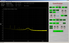
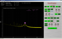
A look at Victor's oscillator on the 339a
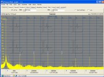
This is Victor's oscillator attenuated to 1Vrms.
Every now and then it breaks into parasitic oscillation.
I have two of these and the parasitic in the other is too much to use the oscillator.
The noise floor is high by comparison and the only harmonic speaks for itself.
This reads 0.00325% on the 339a meter.
Cheers,
Last edited:
I've done more testing of the oscillator and found that adjusting the level trim R30 to yield best distortion at 1KHz is not the best for 10KHz and 20KHz. Adjusting this trim forces the operating voltage level of the Jfet gate to change. Therefore it has become necessary to have one trim pot for each range so the trim can be set appropriately for that range. The difference between 1KHz and 10KHz / 20KHz is 20dB so this is worth going after.
The best way to to do this is to add a wafer to the range selector switch.
Does anyone know where I can find a single or double pole 4 position wafer that will fit the shaft and align with the existing wafers? It need not be exactly the same it just has to fit mechanically.
No amount of fudging with capacitors in the positive feedback loop has any positive effect.
Try separating the AC feedback from the DC. I think one of the schematics I saw had coupling caps on some aspect of the FET. The AGC will change a lot as a function of the component mismatches in the notch networks. The AC linearization of the FET should be independent of the gain of the fet to some degree.
Maybe trimming each R set inside rather than a seperate wafer? Reed relays? Using just the mods: for 1KHz (1 X 1000 dials) and the THD+N at 1.7vac output from the 339A is about .00028% (NO filters are in !)
But, when I change freq dials -the THD goes up to .001% (mostly H2). So I need to trimm for several freqs of popular interest, first.
RM- Take the analysis output from the 725 into an FFT. The fundamental is 425 Hz (I think) regardless of the incoming frequency. The harmonics will line up at multiples of that with the noise essentially gone. If you are looking at harmonics its fantastic and easy to see the relative levels.A little fiddling and you can get the absolute levels of the harmonics. I figure anything below -130dB is not too important.
Its a shame the box is so big. I just don't have room on my bench so mine is in storage a lot.
Oops. I keep forgetting to turn the 400Hz filter off when switching to the lower ranges.
The oscillator is running just couldn't see it on the meter.
Demian how would you go about separating the AC feedback from the DC feedback?
There is a particular setting for the feedback where all ranges are stable but this is not optimal for best distortion in each range. The answer is to have separate setting for each range. I can't fix this with simple equalization on the AC side of things so switching in four different trim pots for each range seems reasonable. The oscillator works fine for the residual of the 339a analyzer. But we are greedy and we want more.
Cheers,
David:
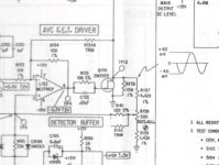
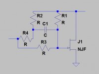
First here is some good background on how the linearization works: http://www.vishay.com/docs/70598/70598.pdf Looking at HP's schematic the linearization is ac coupled (60 pF cap) which means it changes with frequency. Possibly both a trim for DC and a cap coupled (at the wiper) trim for ac in parallel. The sketch shows what I am thinking- R4+R2+C1 are the ac (hf) distortion trim and R3 + R1 are the DC (LF) trim.
Attached is the circuit from the KH4400. It really works but you need something like the 725 to really use it. The trimmer really nulls the 2nd harmonic right out. It takes feedback from the voltage across the fet in positive phase along with a small negative phase (trim resistor) which seem to find the right balance. There are some caps for HF compensation.
Attachments
Hi Demian.... there is an R and C in series across the FET (gate to Drain) as well as in series with the gate. The C value is large --60 Mfd.
I had put a trimmer in place of each R and adjusted. It helped but not a lot and couldnt null out the H2. Changed the 60Mfd to bipolar as well. Maybe a more elaborate network as you show with J1.?
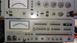
Right now, if i use the X1K range (optimised for that range) and adjust the freq dial from 1 to 10.... It'll cover most freq of interest; 1KHz to 10Khz. The ShibaSoku monitored the 339A generator shows good ageement with the 339A analyzer.. even though the levels are all small and in the lower 10% of the meter range. Good meter.
I get same reading value on both instruments meter displays. Nothing measurable above H2, btw: HP339A at 1KHz is .00023% thd+n and 10KHz it is .0008% thd+n. This is almost usable. I need .0001 or better. I havent replaced some opamps which could further reduce the THD. [And all filters IN on 339A analyzer.]
I can now try the FFT on the 725 analyzer using the .00023%, THD, 1Khz freq. 725 already told me its all second harmonic, though. The 725 will display the level of 2,3,4 and 5th harmonic as well as the total. Will measure Victors osc as well. Thx-RNmarsh
I had put a trimmer in place of each R and adjusted. It helped but not a lot and couldnt null out the H2. Changed the 60Mfd to bipolar as well. Maybe a more elaborate network as you show with J1.?
Right now, if i use the X1K range (optimised for that range) and adjust the freq dial from 1 to 10.... It'll cover most freq of interest; 1KHz to 10Khz. The ShibaSoku monitored the 339A generator shows good ageement with the 339A analyzer.. even though the levels are all small and in the lower 10% of the meter range. Good meter.
I get same reading value on both instruments meter displays. Nothing measurable above H2, btw: HP339A at 1KHz is .00023% thd+n and 10KHz it is .0008% thd+n. This is almost usable. I need .0001 or better. I havent replaced some opamps which could further reduce the THD. [And all filters IN on 339A analyzer.]
I can now try the FFT on the 725 analyzer using the .00023%, THD, 1Khz freq. 725 already told me its all second harmonic, though. The 725 will display the level of 2,3,4 and 5th harmonic as well as the total. Will measure Victors osc as well. Thx-RNmarsh
Last edited:
David:
First here is some good background on how the linearization works: http://www.vishay.com/docs/70598/70598.pdf Looking at HP's schematic the linearization is ac coupled (60 pF cap) which means it changes with frequency.
Yes this is exactly the problem. You can see it monitoring the control voltage on the gate.
It changes with range and frequency.
I can use the summing amplifier which drive the jfet gate in the AGC to sum the signals in.
I'll give it a try.
Cheers,
Hi Demian.... there is an R and C in series across the FET (gate to Drain) as well as in series with the gate. The C value is large --60 Mfd.
I had put a trimmer in place of each R and adjusted. It helped but not a lot and couldnt null out the H2. Changed the 60Mfd to bipolar as well. Maybe a more elaborate network as you show with J1.?
Right now, if i use the X1K range (optimised for that range) and adjust the freq dial from 1 to 10.... It'll cover most freq of interest; 1KHz to 10Khz. The ShibaSoku monitored the 339A generator shows good ageement with the 339A analyzer.. even though the levels are all small and in the lower 10% of the meter range. Good meter.
I get same reading value on both instruments meter displays. Nothing measurable above H2, btw: HP339A at 1KHz is .00023% thd+n and 10KHz it is .0008% thd+n. This is almost usable. I need .0001 or better. I havent replaced some opamps which could further reduce the THD. [And all filters IN on 339A analyzer.]
I can now try the FFT on the 725 analyzer using the .00023%, THD, 1Khz freq. 725 already told me its all second harmonic, though. The 725 will display the level of 2,3,4 and 5th harmonic as well as the total. Will measure Victors osc as well. Thx-RNmarsh
Hi Rick,
Try working the 'Amplitude Adjust' R30 along with the distortion trim.
4 zero's and a 2 --
I have a variable twin-t filter and I applied it to the 1KHz signal from the 339A. I tuned the H2 out and now the distortion is -- .000025% (4 zero's) ! [maybe mostly noise.. have to check with FFT]
Though it will be great to have it all done in one box. I'll follow on further lowering; espec that H2. Thx-RNMarsh
I have a variable twin-t filter and I applied it to the 1KHz signal from the 339A. I tuned the H2 out and now the distortion is -- .000025% (4 zero's) !
[maybe mostly noise.. have to check with FFT] Though it will be great to have it all done in one box. I'll follow on further lowering; espec that H2. Thx-RNMarsh
Attachments
Last edited:
The B&K is also lowering the 3rd and up harmonics (and the fundamental) so its not clear what you are getting. The 725 will go down to .00001% with the ag15. Too many zeros and its easy to get confused.
To tweak the distortion of the HP just select H2 on the 725 and tweak for the lowest.
Attached is a plot of the distortion from the AG16 measured with an AK5394A demo board. All of the harmonics are -124dB or below. This is probably the limitation of the AK5394A since the 725 indicates much less distortion.
I think -120 dB and below for harmonics becomes a point of no real return for effort. No analog recording system ever came close and this is possibly the best digital today.
Attachments
I factored that all in. The input level is adjusted to be at 100%. Some 3rd plus may be attenuated... dont care as it and the other higher H are Much lower than the H2. Besides, thats all for the better.
Now, I'm back to the same situation as before.....but now with the 725; On the lowest range and at 10% of the low end of the meter. Wonder if I can get another -20dB somewhere. One more zero. -Thx RNMarsh
[just kidding]
My interest is in being able to accurately measure my own amplifier designs which are very low analog. Now I can tune them for lowest Harmonic distortion. I want to be at least 10-20dB better than my amp circuits.... which are already pushing the -110 (or more) mark in practice (not sim).
Last edited:
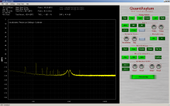
The fundamental is converted to something around 415 Hz I think. Its harmonics are in the output jack with the fundamental removed. The noise is also removed. The FFT will show you.
I have been looking at the simple FFT displays on e-bay to see if one would work for this. No need for exotics.
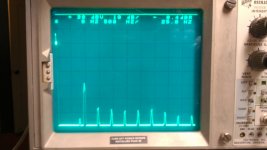
Attached is a snapshot I took of the distortion output measuring Victors oscillator. The tall peak is the 2nd Harmonic. 2-10 are shown in a bandpass to 5 KHz. This does not change with input frequency. You can also sync to the trigger output and see phase relationships.
I have been looking at the simple FFT displays on e-bay to see if one would work for this. No need for exotics.
Attached is a snapshot I took of the distortion output measuring Victors oscillator. The tall peak is the 2nd Harmonic. 2-10 are shown in a bandpass to 5 KHz. This does not change with input frequency. You can also sync to the trigger output and see phase relationships.
Attachments
- Home
- Design & Build
- Equipment & Tools
- Low-distortion Audio-range Oscillator