I put a 50k ohm trim in series with the E1 LDR but didn't observe a drop in second H.
I'm wondering if the 339a oscillator is running a bit high in 2H right now.
The level setting pot is bad and might be getting in the way.
I could use one of Victor's oscillators right about now.
I have an extra 1KHz Victor osc.... ?
I have an extra 1KHz Victor osc.... ?
Are you offering it sale?
My biggest concern is keeping the shipping cost down.
We really get hosed in Canada coming from the US.
Balanced modulators
I've turned my attention back to the balance modulators in the 339a.
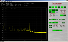
Here is shot of the output of U3A. U3A is the output amplifier for the amplitude error modulator. I soldered 0.33uF cap across R20 which throws the AC common mode balance out. Look at the rise in 2nd H. Also the shoulders that appear on either side of the notch are actually sides band produced by the balanced modulator. I though this was just a product of noise gain about the notch because I see it with Twin T as well.
I thinking a trim some where around U3A may be of use to tighten up the common mode balance. I wondering if a op amp with better CMRR and generally lower distortion and noise may be beneficial?
Thoughts?
I've turned my attention back to the balance modulators in the 339a.
Here is shot of the output of U3A. U3A is the output amplifier for the amplitude error modulator. I soldered 0.33uF cap across R20 which throws the AC common mode balance out. Look at the rise in 2nd H. Also the shoulders that appear on either side of the notch are actually sides band produced by the balanced modulator. I though this was just a product of noise gain about the notch because I see it with Twin T as well.
I thinking a trim some where around U3A may be of use to tighten up the common mode balance. I wondering if a op amp with better CMRR and generally lower distortion and noise may be beneficial?
Thoughts?
Attachments
Bad trim pot.
I tried my own advice and started with the notch circuit balancing. The amplitude notch adjustment does the job pretty well. BUT, on a hunch, I replaced its null pot with a 28 turn cermet type (NTE 500E-0197). Well guess what?! The d**n THD+N dropped in half to .0006 on the meter and 1/2 on the FFT.!!! Have we/HP been limited by a trim pot used since day one? I then changed out the null pot for the freq but it didnt make much difference. Though it is easier to find the null and hold it with a 28 turn control. Try it, pls. This AND the changes you made so far should be killer. Thx-RNMarsh
I tried my own advice and started with the notch circuit balancing. The amplitude notch adjustment does the job pretty well. BUT, on a hunch, I replaced its null pot with a 28 turn cermet type (NTE 500E-0197). Well guess what?! The d**n THD+N dropped in half to .0006 on the meter and 1/2 on the FFT.!!! Have we/HP been limited by a trim pot used since day one? I then changed out the null pot for the freq but it didnt make much difference. Though it is easier to find the null and hold it with a 28 turn control. Try it, pls. This AND the changes you made so far should be killer. Thx-RNMarsh
Last edited:
Richard
Next step- add a pot in series with the LDR (25K?) and increase it until you don't get balance (the LDR doesn't have control any more) then back off and swing the frequency +/- about 3 % and see if you can still get null. I'm sure the engineers at HP went through this exercise with units from tolerance extremes to make sure it balanced in every case. This will reduce the signal across the LDR to its practical minimum. Then series becomes necessary. Two in series will reduce the voltage by 1/2 which may be more than a 6 dB reduction in distortion.
You can get a feel for this from the calibration instructions for the ST1700. There is a long discussion about balancing the network and in effect the LDR's.
I tried my own advice and started with the notch circuit balancing. The amplitude notch adjustment does the job pretty well. BUT, on a hunch, I replaced its null pot with a 28 turn cermet type (NTE 500E-0197). Well guess what?! The d**n THD+N dropped in half to .0006 on the meter and 1/2 on the FFT.!!! Have we/HP been limited by a trim pot used since day one? I then changed out the null pot for the freq but it didnt make much difference. Though it is easier to find the null and hold it with a 28 turn control. Try it, pls. This AND the changes you made so far should be killer. Thx-RNMarsh
Hi Rick,
I put 20 turn cermet's in a long time ago with the same results.
I think you'll find though the result is limited to 1KHz or so.
Notch posistion on TP1
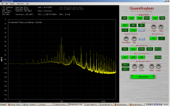
Did you notice from post 964 that there is a frequency doubling going on in the balanced modulators. You can see from the plot the notch is at 2Khzon TP1. That means the modulators are effecting the 3rd not the 2nd by harmonic and directly increasing the 2nd by notch amplitude.
I was wondering why it was the 3rd H going up and down with whatever I did with the modulators and the 2nd stayed relatively the same until the notch was above -80dB or so.
What does the modulator 'gain' affect? Just affect H3? What about giving Demians idea a try? Or can it be actually cancelled? Invert the H2/3 residuals and sum it together or something like that. Thx-RNMarsh [I'm in Calif... is shipping a problem for you from here?]
Last edited:
What does the modulator 'gain' affect? Just affect H3? What about giving Demians idea a try? Or can it be actually cancelled? Invert the H2/3 residuals and sum it together or something like that. Thx-RNMarsh [I'm in Calif... is shipping a problem for you from here?]
Hi Rick,
Someone sent me a PM and offered one of Victor's oscillators. It will ship tomorrow.
Thanks for you offer. I think I only need one.
yes my oscillator need a little work it is running high.
I tweaked it a little and the distortion dropped.
The notch filter is working better than was assumed.
1KHz @ 1Vrms
I get a lot of hash if the input of the analyzer is connected to the oscillator. I'll have to have a look at that to.
Have a look.
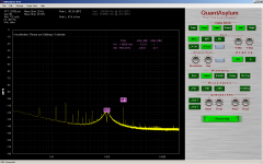
I tweaked it a little and the distortion dropped.
The notch filter is working better than was assumed.
1KHz @ 1Vrms
I get a lot of hash if the input of the analyzer is connected to the oscillator. I'll have to have a look at that to.
Have a look.
Attachments
What does the modulator 'gain' affect? Just affect H3? What about giving Demians idea a try? Or can it be actually cancelled? Invert the H2/3 residuals and sum it together or something like that. Thx-RNMarsh [I'm in Calif... is shipping a problem for you from here?]
I put a trim pot in series with the LDR earlier today but there wasn't any change in 2nd H.
To get the notch this deep you need to change the cap C8 from 47uF to 1uf.
This speeds up the error signal and doesn't have any effect on distortion.
Also it's easier to set the input balance by FFT on TP1 and adjusting.
The noise will drop considerably when there is balance. You can do this at 1KHz.

Excellent performance -Recap the changes --
I can certainly live with that. Its really excelent for a variable oscillator/THD meter thats not real expensive; quick and easy to use for many purposes.
OK... recap. Which mods make the most difference and in what order should I do them... starting with the biggest improvment? Thx-RNmarsh
I got pissed off at the bad pot in the oscillator and ripped it out replacing it one hanging out the bottom of the oscillator.
This what we have and this is not bad.
I can certainly live with that. Its really excelent for a variable oscillator/THD meter thats not real expensive; quick and easy to use for many purposes.
OK... recap. Which mods make the most difference and in what order should I do them... starting with the biggest improvment? Thx-RNmarsh
Last edited:
Those are very good numbers. The Boonton alignment procedure calls for a wave analyzer to tweak the null and it makes the process much easier.
Until I got the Shibasoku stuff I was never sure what I was looking at and which part was misbehaving. Afterwards nothing was hidden and this was all much easier. Victor's oscillator is excellent and inexpensive.
Until I got the Shibasoku stuff I was never sure what I was looking at and which part was misbehaving. Afterwards nothing was hidden and this was all much easier. Victor's oscillator is excellent and inexpensive.
This all started with the suggestion of tapping the notch filter and using the the 339a as a front end for a sound card and FFT. Beyond this I doubt this will improve the analyzer itself.
There are lot more issues to address forward of the notch filter. For example I can't use the analyzer with out the filters in. The noise and or parasitic oscillations are so high the level meter read 0.007% on a -80dB FS. So the idea is to bypass the analyzer all together and that's where my focus has been. The mods and tweaks have been to that end.
I also have to point out that what you see is tweaked at 1KHz and 1Vrms input to the notch filter in isolation. That is, the signal is injected directly into the filter and measured right at the output. I still have to measure the performance with the input amplifiers connected.
There is still a lot of work to do.
Additionally the spectacular notch only works at this calibration frequency and level.
In the x100 range it doesn't perform as well with the notch and that needs to be looked at. But is this really important? We only need a -60dB notch for SC + FFT. The distortion levels are far more important.
But like you said Demian HP designed the 339a to meet there specs and for every unit.
Some might be better than others but all of them will perform to spec. But we want more.
We are trying to milk this thing for everything we can get and I think this mean updating some of the circuits. I think we can make this a useful unit besides just a level meter and oscillator. Dick has an update for the oscillator on his web page. I think the LT1468 works in there.
I'll continue with this tomorrow looking at the input section.
I will summarize what I done so far.
Last edited:
Those are very good numbers. The Boonton alignment procedure calls for a wave analyzer to tweak the null and it makes the process much easier.
Until I got the Shibasoku stuff I was never sure what I was looking at and which part was misbehaving. Afterwards nothing was hidden and this was all much easier. Victor's oscillator is excellent and inexpensive.
Hi Demian,
I have a HP3581C wave analyzer but I didn't want to drag it up from downstairs.
The QA400 markers stay pinned on what ever frequency they're place on and that make it easy to tune the notch. The wave analyzer is a bit noisy at -130dB and that make it difficult at these levels.
Cheers,
David.
stock 339A numbers -
Being able to have a wide range of test freq is a nice convenience. I have all the IC's on hand now that you used so far but waiting to see what else.....
So far the complete HP339A system -- reading its own oscillator at almost stock (osc + analyzer distortion) - with just a tune up and changing the two null trimmers (using a 3580A spect analyzer on the output monitor port of the 339A) -- gives a noise floor of -145. The H2 is -105 and the H3 -130. Its a good beginnng and its getting better!") Thx-RNMarsh
Thx-RNMarsh
Being able to have a wide range of test freq is a nice convenience. I have all the IC's on hand now that you used so far but waiting to see what else.....
So far the complete HP339A system -- reading its own oscillator at almost stock (osc + analyzer distortion) - with just a tune up and changing the two null trimmers (using a 3580A spect analyzer on the output monitor port of the 339A) -- gives a noise floor of -145. The H2 is -105 and the H3 -130. Its a good beginnng and its getting better!
Thx-RNMarsh- Home
- Design & Build
- Equipment & Tools
- Low-distortion Audio-range Oscillator