hey part2wanksta.
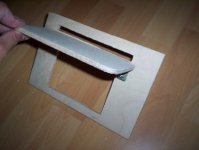
the bracket is made of steel. and the other material is plywood.
here is a german .pdf (thanks to harald from the german diy-community.de)
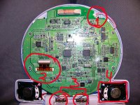
there are some schematics: brightness-mod is yello, reddish mod is red, saturation is the blue schematic.
i only did the brightness mod. i translate:
put the 10 kOhm potentiometer in center-position.
the 20 kOhm is a very small one with many turns (dunno how to translate, just very small ones ). then turn the 20kOhm from bright that it will even get darker. now the 10 kOhm can be used for fine adjustement. that's it.
hope that helps abit.
the bracket is made of steel. and the other material is plywood.
here is a german .pdf (thanks to harald from the german diy-community.de)
there are some schematics: brightness-mod is yello, reddish mod is red, saturation is the blue schematic.
i only did the brightness mod. i translate:
put the 10 kOhm potentiometer in center-position.
the 20 kOhm is a very small one with many turns (dunno how to translate, just very small ones ). then turn the 20kOhm from bright that it will even get darker. now the 10 kOhm can be used for fine adjustement. that's it.
hope that helps abit.
alapimba said:hello, thanks for your reply
Tell me one thing, in other forum one user told me that i could make the image bigger putting the 2nd fresnel (the one between the lcd and the objective at more distance from the lcd.. like 5cm.. it really happends? i tried but i didn't saw any improvement..
Thanks")
that's nonsense as you saw. to make your image bigger at the same throw use a proper spectacle glass with plus diopters.
It'll shorten ur focusing length.
IEF
There are some areas in the pdf I am having trouble understanding.
This section:
Ist dir das Bild dann noch zu farbig, mache 2. Farbsättigungsmod.
Achtung das Bauteil (0,1 uF Kondensator) zwischen den zwei blauen Punkten muss rausgelötet werden! Wenn er ganz bleibt, könnt ihr ihn wieder verwenden, wenn nicht, einfach einen neuen mit Drähten verwenden.
Translates (via Babelfish) to:
You if the picture is then still too colored, make 2. Farbsaettigungsmod.
Attention the construction unit (0.1 UF condenser) between the two blue points must be rausgeloetet!
If it remains whole, can their it again use, if not, simply a new with wires to use.
My take on this is:
If the color saturation of the picture is still off, then make the #2 Mod for saturation.
Caution, the construction unit (0.1 UF condenser) between the two blue points must be rausgeloetet (Cut?)!
Not sure what this means:
If it remains whole, can their it again use, if not, simply a new with wires to use.
Any help in usderstanding this would be appreciated
unit24 said:IEF
There are some areas in the pdf I am having trouble understanding.
This section:
Ist dir das Bild dann noch zu farbig, mache 2. Farbsättigungsmod.
Achtung das Bauteil (0,1 uF Kondensator) zwischen den zwei blauen Punkten muss rausgelötet werden! Wenn er ganz bleibt, könnt ihr ihn wieder verwenden, wenn nicht, einfach einen neuen mit Drähten verwenden.
Translates (via Babelfish) to:
You if the picture is then still too colored, make 2. Farbsaettigungsmod.
Attention the construction unit (0.1 UF condenser) between the two blue points must be rausgeloetet!
If it remains whole, can their it again use, if not, simply a new with wires to use.
My take on this is:
If the color saturation of the picture is still off, then make the #2 Mod for saturation. yepp buddy correct
Caution, the construction unit (0.1 UF condenser) between the two blue points must be rausgeloetet (Cut?)! rausgelötet=soldered out
Not sure what this means:
If it remains whole, can their it again use, if not, simply a new with wires to use. in case the capacitor keeps functioning u can use it in this circuit othérwise use a common capacitor instead of the old one
Any help in usderstanding this would be appreciated
hey unit,
sorry for ma late reply.
hope it helps.
cu ief
Can I dissconect the ribbon cable?
Hi IEF,
About the ribbon cable of the PSONE LCD, can it be unpluged from the controller board so you can manage better the LCD to remove the Backlight?
See the number 2 connector of the image. this is the cable that I'm talking about
Greetings
Hi IEF,
About the ribbon cable of the PSONE LCD, can it be unpluged from the controller board so you can manage better the LCD to remove the Backlight?
See the number 2 connector of the image. this is the cable that I'm talking about
Greetings
Attachments
Thanks thanks for the information alapimba, actually I found that picture in this forum
http://www.lumenlab.com/forums/index.php?showtopic=1770&hl=psone&st=80
In that forum they say not to disconnect the ribbon cable, but the image of the LCD mounting that IEF attach in this thread seems that he had to disconnect it to fit in his design
Greetings
http://www.lumenlab.com/forums/index.php?showtopic=1770&hl=psone&st=80
In that forum they say not to disconnect the ribbon cable, but the image of the LCD mounting that IEF attach in this thread seems that he had to disconnect it to fit in his design
Greetings
Attachments
check the name of the user that post the picture..
By the way.. as they said in that forum i mounted my lcd without disconnect that cable.. but last week acidently i disconnected it.. but later i connected it again and the lcd is working fine so i assume that theres is no problem at all..just do it carefully.
i can't tell the same about the sound. i disconnected the sound and then i tryed to connect again but no sound at all
alapimba said:check the name of the user that post the picture..
UPS I hope that image is not copyrighted

Thanks alapimba for the fast response and for the image
Greetings
eheh no problem.
Keep posting pictures and experiences of your project to so we can learn with each others, as we are both using 5" lcd's and many other ppl use it too..
some pictures of my tests and stuff here:
http://www.irrita-me.com/temp/diy1.jpg
http://www.irrita-me.com/temp/diy2.jpg
http://www.irrita-me.com/temp/diy3.jpg
http://www.irrita-me.com/temp/diy4.jpg
http://www.irrita-me.com/temp/diy5.jpg
http://www.irrita-me.com/temp/diy6.jpg
http://www.irrita-me.com/temp/diy7.jpg
http://www.irrita-me.com/temp/diy8.jpg
http://www.irrita-me.com/temp/diy9.jpg
- Status
- This old topic is closed. If you want to reopen this topic, contact a moderator using the "Report Post" button.
- Home
- General Interest
- Everything Else
- The Moving Image
- DIY Projectors
- 5" Psone w new light engine