It appears that the power board on my LP600 is toast. Nothing appears "burnt" but there are no lights or LCD when it is powered up. The fuse on the board is OK and I'm scratching my head trying to figure out next speps. The board assembly number is 510-1842-16. Every search engine I'[ve tried gets me right back to this forum which does not appear to have a LP600 thread. Any advise from anyone will be much appreciated.
Hi, i have the exact same power here. I will supply some pics soon, just gotta get a hold of a camera.
I did some measurements, but im not sure what to expect where (i only got the power board, not the rest as im trying to fix this for a friend)
Im getting around 2V on the lamp connector and 5ish V on the square connector on the underside of the board. Mate says it doesnt work tho, he tried changing bulb etc and reconned that the power was bad.
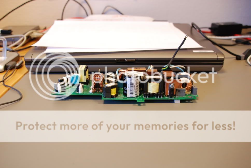
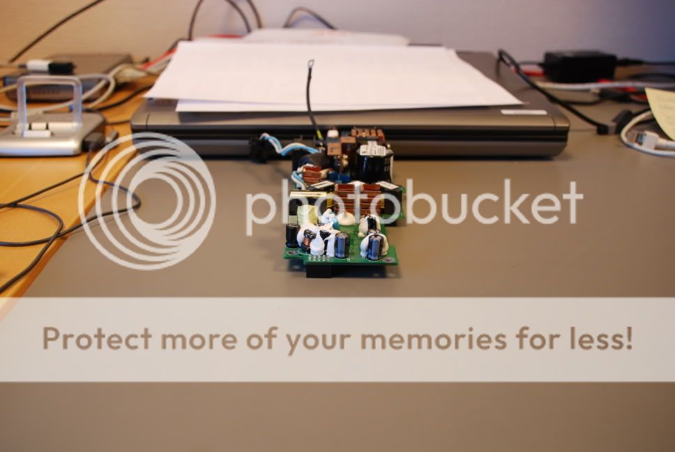
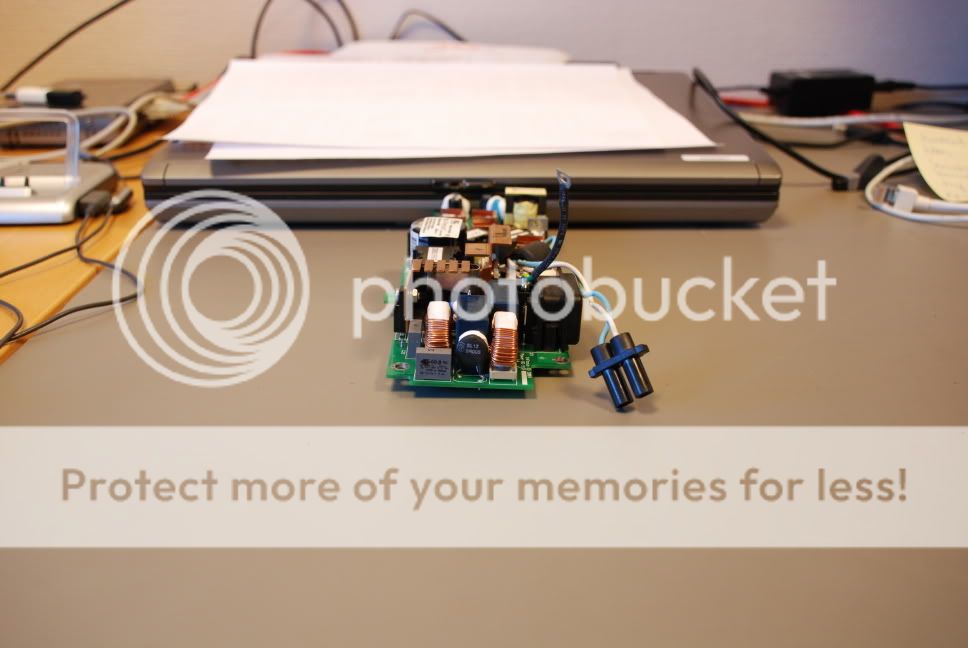
Was not able to edit last post (possibly due to me being a new member) so here is the pictures i promised.
Hope this is what you were looking for!
An externally hosted image should be here but it was not working when we last tested it.
An externally hosted image should be here but it was not working when we last tested it.
An externally hosted image should be here but it was not working when we last tested it.
An externally hosted image should be here but it was not working when we last tested it.
An externally hosted image should be here but it was not working when we last tested it.
An externally hosted image should be here but it was not working when we last tested it.
Hope this is what you were looking for!
Hi!
My first post on this forum.
Seems that I also have same symptoms on InFocus LP600 projector, it is dead.
No LED light, no LCD text or light, no picture, just nothing.
I dismantled and checked fuse, but fuse seems to be OK.
I couldn't find any burn marks on power board or other boards.
So now I'm little bit on dead end.
Have anyone some information about this power boad and specially what voltages should be at the pin grid on working board?
Or could somebody measure voltages from working power board?
Help really appreciated.
Thanks
Pexi
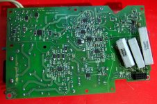
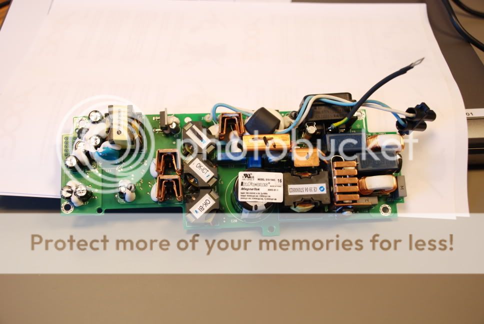
on the mains section of the power supply board you have 4 100uF/16v and 1 4,7uF/35V electrolyt condenser of a 85 degree type. that means it will work 2000 hours at 85 degree (celsius). since the power supply only switch off the lamp in standby with no fan the power supply get hot- i think about 70 degree. so after two years in stanby it is evident that this condensers loose halve of their capacity - after switch off no new start. changing this condensers with new ones of 105 degree type will solve tis problem. and for the future - no more stanby.
Before trying DaGimp's answer, I would do this first...
I just finished a relamping on a projector and it was dead when I took the bulb cover and bulb out. That is, until I put the bulb cover back on. There was a big safety switch that was pressed when the bulb cover is screwed on tight. That was preventing anything from happening and it was puzzling until i started poking around through various holes on the outside.
So that aside, all you people with only a mainboard or power board - this is typically a no-go. Often the PS is controlled by the mainboard, which is controlled by those buttons on the outside. You won't get far without the projector controls. The controls for mine are attached via a ribbon cable to the keypad fixed to the case cover. This would not apply if the buttons were ON the mainboard.
Okay - so try those simple things first... then see if those condesors (capacitors?) are bad.
By the way, DaGimp, do you know how you would actually TEST those components? (without some expensive scope)
Hi!
I managed to buy old working power board quite cheap and made few measeures on that one.
DaGimp were right. I needed to replace only 3 of those 85 C condensers and now power board works nicely. I finally replaced all 5 of them to be certain that it will work longer...
Thanks goes to Shorin and specially DaGimp for right answer.
cheers Pexi
LP600 Power Supply Dead
After a loss of power to the conference room, it appears that the power board on my LP600 is not working. Like the original thread problem, nothing appears "burnt" and there are no lights or LCD when it is powered up. The fuse on my board is OK.
Is there a MOV or other component that typically fails on a loss of power I can easily check?
Does member mbates14 or other member still repair InFocus power supplies? If so, please drop ma an email. I do not plan to send it to InFocus. The MagnetTek power supply number is 510-1842-17.
Thanks - Mike
I know this is a silly question, but after a ton of trying, I can not get the cover off this projector. Is there anything you have to do besides unscrewing the four obvious screws on the corners?
Also, mine has a slightly different problem. The lamp strikes about 10% of the time. Are there problematic capacitors on the lamp ballast or is there something else I should be looking for?
Thanks!
Also, mine has a slightly different problem. The lamp strikes about 10% of the time. Are there problematic capacitors on the lamp ballast or is there something else I should be looking for?
Thanks!
The secret of the LP600 case dis-assembly is to depress the top and bottom cover clips seen through the side panel grills. Proceed gently and the case should separate.
Once separated, the top panel is connected to the main board via a flat ribbon connector. Note the orientation, and slide the retaining clip out a bit from the connector housing (mine is a light tan color) to release the cable.
The remaining dis assembly steps are obvious from this point on.
Observe anti-static precautions and physical stress.
Good luck
LP600 Power Supply Repair
Having heard nothing from members who repair power supplies and the writing off the ridiculously expensive Infocus repair rates, other avenues must be taken. Here is what I have:
justrepairs.com - I have requested arepair estimate but I suspect it will be in the neighborhood of $200.00 plus.
Reverse engineering - the Magnetek power supply in my LP600 is very well constructed but Magnetek support and documentation is non-exisitent as far as I know. So I have begun to have a hard look at this infamous unreliable power supply.
o it is a classic off-line switching supply up to the main capacitor with lots of line filtering - so far so good (this part of the supply is working fine with 170VDC across the cap with the safety interlock defeated)
o there is a 555 timer circuit (used for starting the lamp?)
o the primary controller U1 is a TOPs 245 thru hole and NOT a Viper 100A that may be prime for the lamp voltage
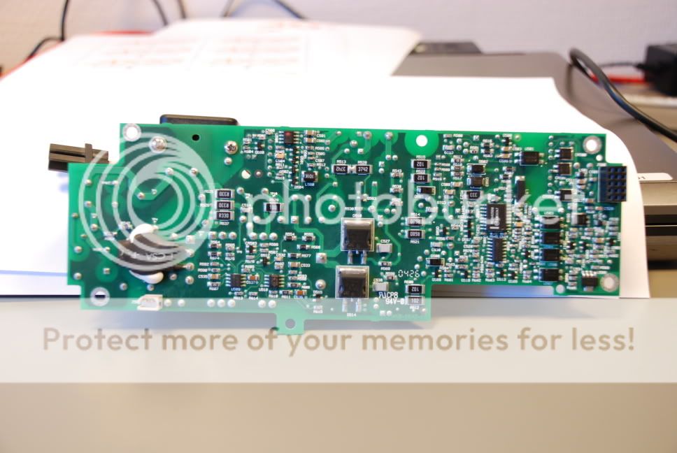
o there is a second PWM controller SMT device underneath that appears to be responsible for the low voltage outputs
o opto-isolators provide the feedback and C1 provides the isolated ground for the outputs (this keeps the user from being electrocuted ;-) )
Initial reaction is that the design is sound but corners were probably cut on component selection to save costs. I'll post more information if I can get this skunk on the bench and track down the culprit.
Having heard nothing from members who repair power supplies and the writing off the ridiculously expensive Infocus repair rates, other avenues must be taken. Here is what I have:
justrepairs.com - I have requested arepair estimate but I suspect it will be in the neighborhood of $200.00 plus.
Reverse engineering - the Magnetek power supply in my LP600 is very well constructed but Magnetek support and documentation is non-exisitent as far as I know. So I have begun to have a hard look at this infamous unreliable power supply.
o it is a classic off-line switching supply up to the main capacitor with lots of line filtering - so far so good (this part of the supply is working fine with 170VDC across the cap with the safety interlock defeated)
o there is a 555 timer circuit (used for starting the lamp?)
o the primary controller U1 is a TOPs 245 thru hole and NOT a Viper 100A that may be prime for the lamp voltage
o there is a second PWM controller SMT device underneath that appears to be responsible for the low voltage outputs
o opto-isolators provide the feedback and C1 provides the isolated ground for the outputs (this keeps the user from being electrocuted ;-) )
Initial reaction is that the design is sound but corners were probably cut on component selection to save costs. I'll post more information if I can get this skunk on the bench and track down the culprit.
Power Supply - On the bench
Today's report from the engineer:
A careful visual under magnification does not reveal any visible faults. Will start at the output of the supply as the mains capacitor is at 170 VDC (normal with a full-wave rectification and 118VAC input).
The output section of this off-line supply is electrically separated from the main section by 1 grounding capacitor, 5 optio isolators and a ~1/2" wide gap in the copper on the circuit board.
Pulled one of the 100uF caps out of the output circuit and checked the ESR (as suggested by member daGimp) which was high. So, this poor supply has been running for about 3 years now and we'll replace those 85oC caps with the 105oC devices for a few cents more each.
Next step - order and replace output caps based on the assumption that if they are dry and out of spec, the opto-isolated feedback to the PWM chip will inhibit start-up.
Will also order a TOPS 245 PWM through-hole device since they are inexpensive and might as well have one around. It is believed that this device is the lamp switcher and the one in the circuit now is probably OK but what's a few dollars with the economy in trouble? The MC34... PWM device will be assumed good for now since it is a SMT device and a bit of a hassle to replace.
Will report back next week when parts are received, installed and another attempt to start the supply on the bench is made.
NOTE: If you are doing this work also, don't forget the lamp cover interlock must be defeated (shorted) for bench testing. This is the 2 port connector on the bottom of the board.
While working on my LP600 over the last couple days, an internet search has indicated that the thermal cutoff used in this projector often goes bad. For those of you that have no power at all, you might want to try shorting this component temporarily to see if that helps.
I'm having a problem with the lamp striking. mmclendon, have you identified the components of the 555 timer circuit? Any ideas as to what might go bad in this circuit? A visual description would be most helpful since there is so much white crap obscuring the component numbering.
I have replaced all of the electrolytic capacitors except for the main and still have the same problem. There appears to be no burnt components. The projector powers on fine, but the lamp strikes only about 10-20% of the time and I get a "retrying" message on the LCD. Once it is on, the output seems pretty stable.
Lamp Striking Circuit
hypa_dude:
If possible, on a bench, are you equipped to load the lamp output with say a 1K ohm 5 watt resistor and scope the high voltage pulse from the starter circuit? Careful of the 30-50KV voltage - don't blow your scope up. That may give you some insight into whether the strike pulse is running only 10-20% of the time or if it is consistent every time (which may indicate that a deteriorating lamp is the problem).
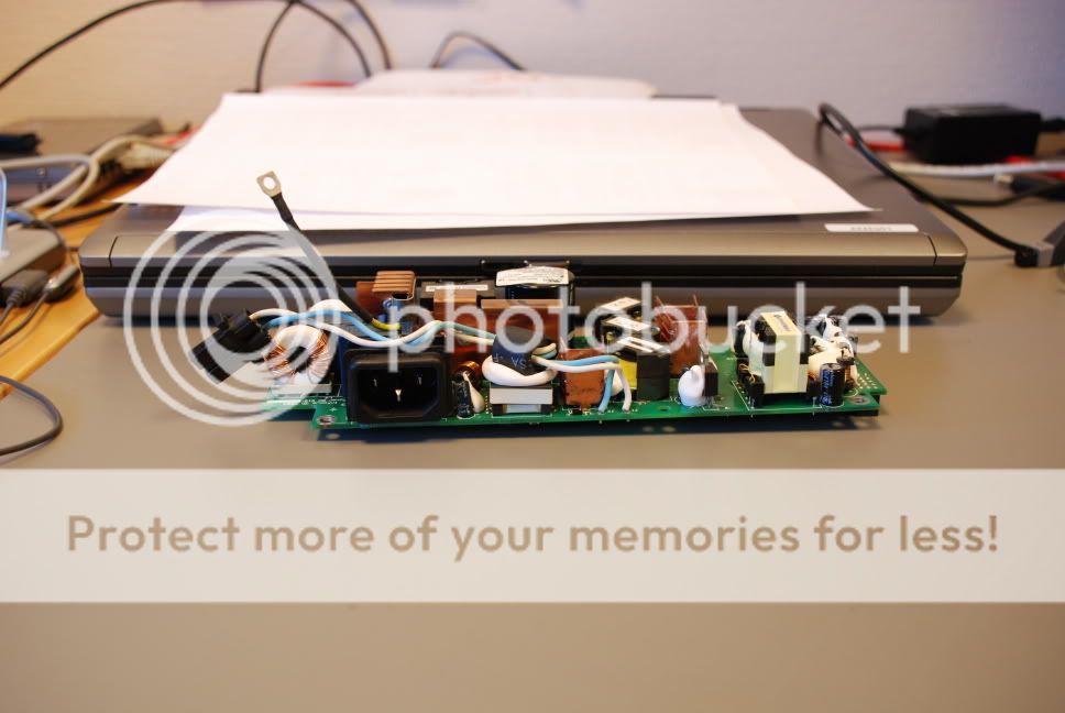
I am guessing that the transformer under the ferrite bead over the lamp cable is the High Voltage pulse transformer. It is likely fed pulses from the NE555 timer circuit driving an ouput transistor. This circuit appears to be configured directly under this HV transformer.
Just thinking about it (wish we had a schematic) the HV start pulse must be superimposed on the 80VDC lamp running voltage. That means that there is likely an inductor in line with the 80 VDC to keep the start current from flowing into the low impedance of the 80VDC supply. This is another area to check.
hypa_dude:
If possible, on a bench, are you equipped to load the lamp output with say a 1K ohm 5 watt resistor and scope the high voltage pulse from the starter circuit? Careful of the 30-50KV voltage - don't blow your scope up. That may give you some insight into whether the strike pulse is running only 10-20% of the time or if it is consistent every time (which may indicate that a deteriorating lamp is the problem).
I am guessing that the transformer under the ferrite bead over the lamp cable is the High Voltage pulse transformer. It is likely fed pulses from the NE555 timer circuit driving an ouput transistor. This circuit appears to be configured directly under this HV transformer.
Just thinking about it (wish we had a schematic) the HV start pulse must be superimposed on the 80VDC lamp running voltage. That means that there is likely an inductor in line with the 80 VDC to keep the start current from flowing into the low impedance of the 80VDC supply. This is another area to check.
- Status
- This old topic is closed. If you want to reopen this topic, contact a moderator using the "Report Post" button.
- Home
- General Interest
- Everything Else
- The Moving Image
- DIY Projectors
- InFocus LP600 Power Board Questions