no no no. dont scope a startup pulse.
there are 0.1uf 400v starter charge pump caps that need looked at, along with the coupling cap.
youll need an analog ESR meter to read these for opens. on a TENMA brand analog ESR meter, they will check somewhere around 20 ohms. if the needle barely moves, or doesnt move at all (assuming the meter is calibrated). then the cap is bad and should be replaced.
Re: Power Supply - On the bench
SUCCESS! Replacing the output caps with high ESR allowed the supply to start and run just fine. They were difficult to find but the 105o parts were used to try to extend the power supply life.
ROOT CAUSE of FAILURE: There is really nothing wrong with the Magnetek power supply design. However, the InFocus system design has a serious flaw in the power supply cooling when the unit is in standby ( only whatever convection cooling is available). So the unit that sits in standby for a period of time bakes the caps and one day, the baked caps in the control loop are in such bad condition, the supply cannot start up if it ever loses power. If you have these projectors installed permanently, remove the power completely when not in use. The lightning bolts at InFocus should warn the user about the issue. Thanks again daGimp for the lead.
mmclendon said:Today's report from the engineer:
A careful visual under magnification does not reveal any visible faults. Will start at the output of the supply as the mains capacitor is at 170 VDC (normal with a full-wave rectification and 118VAC input).
The output section of this off-line supply is electrically separated from the main section by 1 grounding capacitor, 5 optio isolators and a ~1/2" wide gap in the copper on the circuit board.
Pulled one of the 100uF caps out of the output circuit and checked the ESR (as suggested by member daGimp) which was high. So, this poor supply has been running for about 3 years now and we'll replace those 85oC caps with the 105oC devices for a few cents more each.
Next step - order and replace output caps based on the assumption that if they are dry and out of spec, the opto-isolated feedback to the PWM chip will inhibit start-up.
Will also order a TOPS 245 PWM through-hole device since they are inexpensive and might as well have one around. It is believed that this device is the lamp switcher and the one in the circuit now is probably OK but what's a few dollars with the economy in trouble? The MC34... PWM device will be assumed good for now since it is a SMT device and a bit of a hassle to replace.
Will report back next week when parts are received, installed and another attempt to start the supply on the bench is made.
NOTE: If you are doing this work also, don't forget the lamp cover interlock must be defeated (shorted) for bench testing. This is the 2 port connector on the bottom of the board.
You are correct to some extent, but your analysis is wrong.
there IS a design flaw to the infocus magnatek power supply.
If you look, the only cap that actually goes bad is the 100uf cap right behind the chopper controller output IC.
Why? if you look, for one, this chip has no heatsink, and 2, the capacitor is right behind it directly against it. this allows the heat to transfer from the chip streight into the capacitor, almost like they did this directly on purpose so it will fail soon.
remedy for that is to put the new capacitor in, but only push it in a little bit, soldering it in. which will have super long leads. then bend the capacitor over, away from the heat of the IC.
problem solved.
question for mbates
Not sure if you can answer this mbates, but are you referring to the capacitor at location C3 on that board? Thanks!
Why? if you look, for one, this chip has no heatsink, and 2, the capacitor is right behind it directly against it. this allows the heat to transfer from the chip streight into the capacitor, almost like they did this directly on purpose so it will fail soon.
Not sure if you can answer this mbates, but are you referring to the capacitor at location C3 on that board? Thanks!
This projector is kicking my butt.. Same problem, worked fine, power went out no lights.. Managed to get it going a few months ago was fine until power outage then back to same problem.
Where do I get these caps? I have a kids party in a few weeks and would like to give it a shot before I pull the trigger on a new one..
Or of anyone out there does a repair at a reasonable rate??
Thanks,
Chuck
Where do I get these caps? I have a kids party in a few weeks and would like to give it a shot before I pull the trigger on a new one..
Or of anyone out there does a repair at a reasonable rate??
Thanks,
Chuck
Will these work?
http://www.parts-express.com/pe/showdetl.cfm?Partnumber=020-1704
And I know this isnt' the high temp one but will it at least fix the problem?
http://www.parts-express.com/pe/pshowdetl.cfm?&Partnumber=020-1138
http://www.parts-express.com/pe/showdetl.cfm?Partnumber=020-1704
And I know this isnt' the high temp one but will it at least fix the problem?
http://www.parts-express.com/pe/pshowdetl.cfm?&Partnumber=020-1138
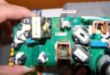
mbates14 said:You are correct to some extent, but your analysis is wrong.
there IS a design flaw to the infocus magnatek power supply.
If you look, the only cap that actually goes bad is the 100uf cap right behind the chopper controller output IC.
Why? if you look, for one, this chip has no heatsink, and 2, the capacitor is right behind it directly against it. this allows the heat to transfer from the chip streight into the capacitor, almost like they did this directly on purpose so it will fail soon.
remedy for that is to put the new capacitor in, but only push it in a little bit, soldering it in. which will have super long leads. then bend the capacitor over, away from the heat of the IC.
problem solved.
Followed these directions, replaced that one cap, back up and running. Also took your advice and left some leads on the top and moved it away from the IC. See attached pic..
Attachments
gtcali said:
Yup...
Gentlemen, after many hours of searching I think you are going to be my saviours!
I have an Infocus Screenplay 5700 which has a failing power supply. Essentially it won't power up, the fans just idle. If (as advised by a TV repair engineer I know) I apply a hot hair dryer through the side of the PJ aimed at the PSU - after 30 seconds or so, it fires up and works perfectly. He told me that this is common in old TVs where CAPs need to be warmed up to function as they are old.
So.... (I'm not in touch with the engineer - I'm in another country now) - I took the PJ apart today to try and isolate which cap or caps to replace. Thing is, they all look fine") - I used a basic DMM to test rising resistance, which they all passed, but to be honest the figures didn't mean anything to me. All I could see is that the resistence would climb , at varying speeds for each cap, then fall if I reversed polarity of my meter.
- I used a basic DMM to test rising resistance, which they all passed, but to be honest the figures didn't mean anything to me. All I could see is that the resistence would climb , at varying speeds for each cap, then fall if I reversed polarity of my meter.
Anyhow - with these pics - could you possibly identify the "area" of capacitors I should replace with new 105 degree ones. I could buy all 11 electrolytics that I can see but then I'd be throwing away a fair amount of money, and any extra soldering increases my risk of messing it up.
The 1st pic below is an overview of the PSU
Next, Below, close up of main bank of caps: - From what I can read there are 6 x 16v 680uf caps and 1 x 100uf 16v
Next, Below, Huge 450v 270uf 85 degree cap on PSU
Next, below, if I'm not mistaken, is the balast, which is fine I guess, as the PJ works once given the hairdryer-start!
Finally, close up of, what I think is the balast, cap - 450v 47uf
I'm making the assumption based on all the other posts on here that I'm looking in the right place? I'm perfectly capable of replacing caps. Just really looking to make sure I'm on the right path....
I have an Infocus Screenplay 5700 which has a failing power supply. Essentially it won't power up, the fans just idle. If (as advised by a TV repair engineer I know) I apply a hot hair dryer through the side of the PJ aimed at the PSU - after 30 seconds or so, it fires up and works perfectly. He told me that this is common in old TVs where CAPs need to be warmed up to function as they are old.
So.... (I'm not in touch with the engineer - I'm in another country now) - I took the PJ apart today to try and isolate which cap or caps to replace. Thing is, they all look fine
- I used a basic DMM to test rising resistance, which they all passed, but to be honest the figures didn't mean anything to me. All I could see is that the resistence would climb , at varying speeds for each cap, then fall if I reversed polarity of my meter.Anyhow - with these pics - could you possibly identify the "area" of capacitors I should replace with new 105 degree ones. I could buy all 11 electrolytics that I can see but then I'd be throwing away a fair amount of money, and any extra soldering increases my risk of messing it up.
The 1st pic below is an overview of the PSU
An externally hosted image should be here but it was not working when we last tested it.
Next, Below, close up of main bank of caps: - From what I can read there are 6 x 16v 680uf caps and 1 x 100uf 16v
An externally hosted image should be here but it was not working when we last tested it.
Next, Below, Huge 450v 270uf 85 degree cap on PSU
An externally hosted image should be here but it was not working when we last tested it.
Next, below, if I'm not mistaken, is the balast, which is fine I guess, as the PJ works once given the hairdryer-start!
An externally hosted image should be here but it was not working when we last tested it.
Finally, close up of, what I think is the balast, cap - 450v 47uf
An externally hosted image should be here but it was not working when we last tested it.
I'm making the assumption based on all the other posts on here that I'm looking in the right place? I'm perfectly capable of replacing caps. Just really looking to make sure I'm on the right path....
Small update - I metered the 100uf 16v cap and it only climbed a little in resistance - though it was on the board. I removed it and it metered fine. I put another in anyhow as I had one lying around (25v 100uf).
I changed that one as it seemes a popular one to fail.
So still have the problem. I did notice that I have small a blue quare cap right by one of the FET/transistors - maybe that little fellow is getting hot? It meters fine as far as I can tell though - in situ.
Perhaps I should just buy loads of the smallish caps and replace the lot? Don't fancy stripping the PJ down too many times - and I can't test until it is all back together each time as the fan power for the lamp comes from contacts on the case lid. That and the PCB gets in the way.
OK guys - I've kind of realised that this is a DIY PJ building forum section, and not a free for all tech support
Could I just ask for a little advice. I've done some more reading and as I have to use a hair dryer to get my PSU going, it looks like my startup capacitor is the guilty item. Thing is - what am I looking for to find the startup capacitor? Would it most likely be the massive 450v one?
As I can start the PJ with the application of externl heat, I really don't want to destroy it any further - a hard to start PJ is better than a dead one
This forum is the only place I've found where people know what they are talking about. Any help in teh right direction would be most appreciated.
Apologies in advance if everyone happens to be on holiday at the moment..
- Status
- This old topic is closed. If you want to reopen this topic, contact a moderator using the "Report Post" button.
- Home
- General Interest
- Everything Else
- The Moving Image
- DIY Projectors
- InFocus LP600 Power Board Questions