quantran said:Now I only use it as a transport. It's very nice that the laser unit can be replace easily for ten bucks.
Don't take this the wrong way, but wouldn't it be better to use a cheap new universal player for a transport? I'd have thought that'd be better. The good thing about the cd63 is the lovely sound you can get out of it with modding.
Simon
quantran said:...
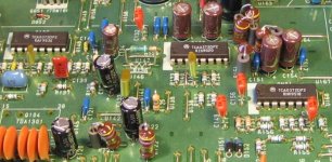
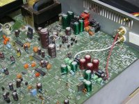
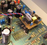
These are the orange 0.1uF and 0.047uF capacitors in the digital / transport control section. I replaced them with RIFA PHE426 series (same value) and the player didn't work with these RIFAs.
You mean like the three orange ones around the TCA? Very strange. Maybe the player doesn't like RIFA
 .
.Ray
Attachments
This red one is measured 2V when running. I have some green LEDs that give 3V.
disco said:
Does the red LED give the same voltage as a green?
Jaap
I have not tried any universal players but I have a Pioneer DVDP and a Sony CDP-227ESD. Both these sound worse than the Marantz as a transport. The XO does help a lot, I think.SimontY said:
Don't take this the wrong way, but wouldn't it be better to use a cheap new universal player for a transport? I'd have thought that'd be better. The good thing about the cd63 is the lovely sound you can get out of it with modding.
Simon
6h5c said:
You mean like the three orange ones around the TCA? Very strange. Maybe the player doesn't like RIFA
Ray
Yes, these caps.
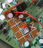
I used hot melt glue also, not sure what everyone else uses to mount their bits ?
Plastic pcb supports are good, worthwhile keeping some of these to hand, like the ones you can cut to size.
When mounting other than horizontal, watch all those electrons dont run to the bottom
Plastic pcb supports are good, worthwhile keeping some of these to hand, like the ones you can cut to size.
When mounting other than horizontal, watch all those electrons dont run to the bottom
quantran said:Yes, these caps.
Nice photo's, Quan. I can't explain why the player behaves so strange just by swapping those caps. It never occurred with the players i've done so far.
ImSparticus said:I used hot melt glue also, not sure what everyone else uses to mount their bits ?
Plastic pcb supports are good, worthwhile keeping some of these to hand, like the ones you can cut to size.
When mounting other than horizontal, watch all those electrons dont run to the bottom
I actually drilled a hole in my PCB

Ray
Attachments
quantran said:
I have not tried any universal players but I have a Pioneer DVDP and a Sony CDP-227ESD. Both these sound worse than the Marantz as a transport. The XO does help a lot, I think.
Ahha, so you did try
6h5c said:
I can't explain why the player behaves so strange just by swapping those caps.
Hi.
Unless the caps are faulty ( DC leak)
Andy
quantran said:This is also an interesting point:
When I replaced all Philips MKT caps in the digital section with good quality MKP of the same value, the CDP didn't work. I had to restore the original orange philips MKT caps then it work fine.
Hi.
Why did you replace these caps?
What were you hoping to achieve ?
Andy
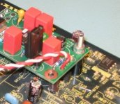
ImSparticus said:I used hot melt glue also, not sure what everyone else uses to mount their bits ?
Plastic pcb supports are good, worthwhile keeping some of these to hand, like the ones you can cut to size.
When mounting other than horizontal, watch all those electrons dont run to the bottom
Bolt them electrons down man, can't have 'm running around!
Attachments

I did not expect much. I have some of these caps lying around. They are good quality caps so when I took out the board to do some other things I put them in to try.
It's very unlikely that these caps are leaking. here is the data sheet http://www.evoxrifa.com/cap_catalog/pulsecap/phe426.pdf
It's very unlikely that these caps are leaking. here is the data sheet http://www.evoxrifa.com/cap_catalog/pulsecap/phe426.pdf
Attachments
rh5c,
Seeing as you are the originator of this impossibly long thread, and while I am trying to work my way through all the posts so I get it right, I saw another thread mentioning some possible typo errors in the TNT blurb, as follows, and was wondering if your mods list already reflects this? My wife will be doing all the work on a CD67SE (as she is an EE) as sort of project for me, but I'd be grateful for a really really simple list.... which I think yours goes some way to providing.
In addition, I have been though so many posts my head hurts, but I was trying to put together a "to do" hit list. Any comments on this one?
A. Analogue Circuit Mods:
1. Set of 2# Burr Brown OPA 2604 op-amps (or possibly 2# LM6172 from National Semiconductor or possibly LC Audio AD8065) to replace the original JRC 2114D op-amps. Install (solder in) sockets first, then you can plug in the old ones and plug in the new ones when they arrive. "I am waiting for some Browndog pcbs to arrive so I can replace the OPA2134 with OPA627?"
2. Set of 4# 3.6kOhm resistors. On the underside of the board, you will have to solder these four small 3.6K-ohm resistors--one from pin 4 to pin 1 and another from pin 4 to pin 7 on EACH of the OPA2604's (take them out of the sockets first, if you're smart!).
2a. Buy and place an over-the-cord "clamp-on" low-Q choke (see Radio Shack for yours).
3a. Set of 4# 100uF High Quality Audio Capacitor (e.g. Elna Starget, Black Gate, Sanyo SG Series OS-Con, Nichicon Muse). The Circuit-board denominators are C611,612,613,614. May not be required on 67SE as Starget may be already in place).
3b. By-pass all replaced capacitors with plastic film capacitors. Stick a 10-22nF Film bypass Cap across each Capacitor. You can use 22nF 63 Volt WIMA ones. As these have recently become scarce, suggested is to use Panasonic "stacked film" SMD Capacitors instead. These are carried by Digi-Key in the US and RS/Farnell in the UK. Any value from 22-100nF will be okay, but it makes sense to go for the highest available voltage rating.
3c. Set of 4# Nichicon FX 4700uf/63v Muse caps where C803, C804, C805 and C806 use to be. Caps all to be bypassed with some Wima 22nF/63v electroytics.
4. Replace the Filter capacitors. Use a set of Philips 1% Polystyrene Capacitors. The Circuit-board denominators are CD21, CD22, CD23, CD24 (120pF); C605, C606(1000pF) and C607, C608 (100pF). i.e. 4# 120pF, 2#1000pF, 2# 100pF.
5a. Remove the 2# electrolytic Capacitors which are "back-to-back" per Channel. These are C655, C656, C657, C658. In the SE-Models (and KI-Signature) they are ELNA "Silmic" 220uF units. Take them out. The CD-57 and 67 use standard units. They do not block any (significant) DC and are considered safe to remove. Just unsolder them and replace with a piece of (high quality coax) cable*. If you have the 67SE and removed them you will now have "2# Silmic Caps" spare.
5b. Use these 2# Silmic Caps (from 5a) to replace the Output Buffer's PSU-Capacitors (C651, C652, C653, C654) and again bypass them with 22nF WIMA Film-Cap's (See 3b above).
6. Replace R613 to R616 (4#) and R651 to R654 (4#) with (Total 8#) 2.2mH Axial Inductors with a measured DC of 1.5 Ohm. This is a much better solution than just shortening these resistors out (as suggested by a number of folks).
7. The Circuit uses two Transistors to Mute the Player on Power-up. Just unsolder QN05, QN06, QN07, QN08. You may however want to hang on to them, as one fellow Internetter disliked what he heard after removing the Muting Transistors in his Pioneer CD-Player.
8. Replace the standard diodes with SCHOTTKY types. PS diodes D801-D804 and D811-D812 replaced with Hexfred soft recovery diodes.
* COAXES. NOTE: FOR ALL COAX CABLES USE RG196. IT IS SMALL IN DIA., ONLY ABOUT .080, AND IT WILL NOT MELT.
B. Digital Circuit Mods:
1. Place IC Shielding with thin copper sheet.
2. Replace RD01, RD04 (near the DAC-Chip) R117, R118, RF01 (near the Micro-Processor Chip - between that Chip and the Transport) with total 5# 1mH miniature Chokes (14 Ohm DCR). Enter three small Ferrite-Beads each (sold in bags of 10 for pennies). These are threaded onto the leads of the Choke, usefully extending the effectiveness to very high frequencies. Note! "R117 and R118 should be R122 and R123" http://www.diyaudio.com/forums/showthread.php?threadid=50684
3. Replace C126 (on the small board attached to the Transport), C157, C114, C120, CF02 (all 47uF 16V), Total 5# with either (a) Nichicon PL Series ultra low ESR Types 100uF 50Volt or (b) Panasonic HFQ 120uF/25Volt (sold in the States by Digi-Key or (c) Elna RSH should work too. Please do not use "Super-low-Z" units (like the Panasonic FA Series). Note! One of the capacitors should be C122 instead of C157 or C114. I believe R122, R123,C120 and C122 "belong" together since they are parts for the TDA1301T (Q104) local powersupply." http://www.diyaudio.com/forums/showthread.php?threadid=50684
4. Replace CD04 & CD07 (2#) with 220uF/50Volt Nichicon PL Units.
5. Replace CD15, CD16 (2#) with 470uF 50Volt. Here I removed the original ceramics (CD04, CD06, CD12, CD13) in order to place my 100nF SMD Caps as close to the Pin's of the DAC as possible. Again, soldering these SMD Units is a tricky job. Steady hands and a small Soldering iron are a must. DO NOT REMOVE ANY OF THE ORIGINAL CERAMICS UNLESS YOU REPLACE THEM!!
6. Replace the standard 50 PPM (parts per million) crystal with a quality 5 PPM crystal.
7. Replace the clock with Elso's Kwak Clock 7 PCB (can build yourself quite cheap) or LC audio XO3 clock $450 or (much cheaper, perform clockerectomy as per http://db.audioasylum.com/cgi/m.mpl?forum=tweaks&n=20123&highlight=Cheap&r=&session= and "Clock Mod" at http://www.acoustica.org.uk/t/63/63hacks.html.
Best two sites for SIMPLE mods
http://www.rjbaudio.com/Audiofiles/MarantzCD67SE.html
http://home.netcarrier.com/~rstevens/cd67semods.html
Complicated Descriptions
http://www.tnt-audio.com/clinica/cd67.html
http://db.audioasylum.com/cgi/m.pl?forum=digital&n=7856&highlight=bobwire+coax&r=&session=
Fix the Tray/Laser/Replace Controller Chip
1. Replace the Controller TDA1301T - SMD ? Hard to get? Philips has a new chip that does what the TDA1301T's job + more functions. Another suspect could be the TCA0372DP2 (14 pin IC nearest the RF Board) that controls the focus of the laser head & links to the servo. This are thru-hole & can be changed relatively painlessly.
2. Replace the CDM12.1 with a Philips VAM1201/1202 laser/tray mechanism.
k.
Seeing as you are the originator of this impossibly long thread, and while I am trying to work my way through all the posts so I get it right, I saw another thread mentioning some possible typo errors in the TNT blurb, as follows, and was wondering if your mods list already reflects this? My wife will be doing all the work on a CD67SE (as she is an EE) as sort of project for me, but I'd be grateful for a really really simple list.... which I think yours goes some way to providing.
from http://www.diyaudio.com/forums/showthread.php?threadid=50684R117 and R118 should be R122 and R123
also from http://www.diyaudio.com/forums/showthread.php?threadid=50684One of the capacitors should be C122 instead of C157 or C114. I believe R122, R123,C120 and C122 "belong" together since they are parts for the TDA1301T (Q104) local powersupply.
In addition, I have been though so many posts my head hurts, but I was trying to put together a "to do" hit list. Any comments on this one?
A. Analogue Circuit Mods:
1. Set of 2# Burr Brown OPA 2604 op-amps (or possibly 2# LM6172 from National Semiconductor or possibly LC Audio AD8065) to replace the original JRC 2114D op-amps. Install (solder in) sockets first, then you can plug in the old ones and plug in the new ones when they arrive. "I am waiting for some Browndog pcbs to arrive so I can replace the OPA2134 with OPA627?"
2. Set of 4# 3.6kOhm resistors. On the underside of the board, you will have to solder these four small 3.6K-ohm resistors--one from pin 4 to pin 1 and another from pin 4 to pin 7 on EACH of the OPA2604's (take them out of the sockets first, if you're smart!).
2a. Buy and place an over-the-cord "clamp-on" low-Q choke (see Radio Shack for yours).
3a. Set of 4# 100uF High Quality Audio Capacitor (e.g. Elna Starget, Black Gate, Sanyo SG Series OS-Con, Nichicon Muse). The Circuit-board denominators are C611,612,613,614. May not be required on 67SE as Starget may be already in place).
3b. By-pass all replaced capacitors with plastic film capacitors. Stick a 10-22nF Film bypass Cap across each Capacitor. You can use 22nF 63 Volt WIMA ones. As these have recently become scarce, suggested is to use Panasonic "stacked film" SMD Capacitors instead. These are carried by Digi-Key in the US and RS/Farnell in the UK. Any value from 22-100nF will be okay, but it makes sense to go for the highest available voltage rating.
3c. Set of 4# Nichicon FX 4700uf/63v Muse caps where C803, C804, C805 and C806 use to be. Caps all to be bypassed with some Wima 22nF/63v electroytics.
4. Replace the Filter capacitors. Use a set of Philips 1% Polystyrene Capacitors. The Circuit-board denominators are CD21, CD22, CD23, CD24 (120pF); C605, C606(1000pF) and C607, C608 (100pF). i.e. 4# 120pF, 2#1000pF, 2# 100pF.
5a. Remove the 2# electrolytic Capacitors which are "back-to-back" per Channel. These are C655, C656, C657, C658. In the SE-Models (and KI-Signature) they are ELNA "Silmic" 220uF units. Take them out. The CD-57 and 67 use standard units. They do not block any (significant) DC and are considered safe to remove. Just unsolder them and replace with a piece of (high quality coax) cable*. If you have the 67SE and removed them you will now have "2# Silmic Caps" spare.
5b. Use these 2# Silmic Caps (from 5a) to replace the Output Buffer's PSU-Capacitors (C651, C652, C653, C654) and again bypass them with 22nF WIMA Film-Cap's (See 3b above).
6. Replace R613 to R616 (4#) and R651 to R654 (4#) with (Total 8#) 2.2mH Axial Inductors with a measured DC of 1.5 Ohm. This is a much better solution than just shortening these resistors out (as suggested by a number of folks).
7. The Circuit uses two Transistors to Mute the Player on Power-up. Just unsolder QN05, QN06, QN07, QN08. You may however want to hang on to them, as one fellow Internetter disliked what he heard after removing the Muting Transistors in his Pioneer CD-Player.
8. Replace the standard diodes with SCHOTTKY types. PS diodes D801-D804 and D811-D812 replaced with Hexfred soft recovery diodes.
* COAXES. NOTE: FOR ALL COAX CABLES USE RG196. IT IS SMALL IN DIA., ONLY ABOUT .080, AND IT WILL NOT MELT.
B. Digital Circuit Mods:
1. Place IC Shielding with thin copper sheet.
2. Replace RD01, RD04 (near the DAC-Chip) R117, R118, RF01 (near the Micro-Processor Chip - between that Chip and the Transport) with total 5# 1mH miniature Chokes (14 Ohm DCR). Enter three small Ferrite-Beads each (sold in bags of 10 for pennies). These are threaded onto the leads of the Choke, usefully extending the effectiveness to very high frequencies. Note! "R117 and R118 should be R122 and R123" http://www.diyaudio.com/forums/showthread.php?threadid=50684
3. Replace C126 (on the small board attached to the Transport), C157, C114, C120, CF02 (all 47uF 16V), Total 5# with either (a) Nichicon PL Series ultra low ESR Types 100uF 50Volt or (b) Panasonic HFQ 120uF/25Volt (sold in the States by Digi-Key or (c) Elna RSH should work too. Please do not use "Super-low-Z" units (like the Panasonic FA Series). Note! One of the capacitors should be C122 instead of C157 or C114. I believe R122, R123,C120 and C122 "belong" together since they are parts for the TDA1301T (Q104) local powersupply." http://www.diyaudio.com/forums/showthread.php?threadid=50684
4. Replace CD04 & CD07 (2#) with 220uF/50Volt Nichicon PL Units.
5. Replace CD15, CD16 (2#) with 470uF 50Volt. Here I removed the original ceramics (CD04, CD06, CD12, CD13) in order to place my 100nF SMD Caps as close to the Pin's of the DAC as possible. Again, soldering these SMD Units is a tricky job. Steady hands and a small Soldering iron are a must. DO NOT REMOVE ANY OF THE ORIGINAL CERAMICS UNLESS YOU REPLACE THEM!!
6. Replace the standard 50 PPM (parts per million) crystal with a quality 5 PPM crystal.
7. Replace the clock with Elso's Kwak Clock 7 PCB (can build yourself quite cheap) or LC audio XO3 clock $450 or (much cheaper, perform clockerectomy as per http://db.audioasylum.com/cgi/m.mpl?forum=tweaks&n=20123&highlight=Cheap&r=&session= and "Clock Mod" at http://www.acoustica.org.uk/t/63/63hacks.html.
Best two sites for SIMPLE mods
http://www.rjbaudio.com/Audiofiles/MarantzCD67SE.html
http://home.netcarrier.com/~rstevens/cd67semods.html
Complicated Descriptions
http://www.tnt-audio.com/clinica/cd67.html
http://db.audioasylum.com/cgi/m.pl?forum=digital&n=7856&highlight=bobwire+coax&r=&session=
Fix the Tray/Laser/Replace Controller Chip
1. Replace the Controller TDA1301T - SMD ? Hard to get? Philips has a new chip that does what the TDA1301T's job + more functions. Another suspect could be the TCA0372DP2 (14 pin IC nearest the RF Board) that controls the focus of the laser head & links to the servo. This are thru-hole & can be changed relatively painlessly.
2. Replace the CDM12.1 with a Philips VAM1201/1202 laser/tray mechanism.
k.
Hi, and welcome to this thread .
To start with the answer to your first question, about the different component numbers: the guys in the thread you linked to are mixing up the two different models CD63 and CD67. You'll see that R117 and R118 do exist for the CD67, the model which Thorsten's article is all about. Same goes for C120 and 122. If you study the 67 manual everything will fall into place. You can get it off my website, along with the latest modslist if you don't have it already.
I'm not sure why you would want to replace the TDA1301T and/or the driver IC's TCA0372 though. The extra 'functions' the first one would have are probably not accessible because the player is not designed for it, and the driver IC's are nothing more than beefy opamps. These chips are not present in a CD67 anyway.
This thread has indeed become impossibly long, but your to-do list looks very good. I think you can get a lot of improvement after you finished all the mods.
Regards,
Ray
.To start with the answer to your first question, about the different component numbers: the guys in the thread you linked to are mixing up the two different models CD63 and CD67. You'll see that R117 and R118 do exist for the CD67, the model which Thorsten's article is all about. Same goes for C120 and 122. If you study the 67 manual everything will fall into place. You can get it off my website, along with the latest modslist if you don't have it already.
I'm not sure why you would want to replace the TDA1301T and/or the driver IC's TCA0372 though. The extra 'functions' the first one would have are probably not accessible because the player is not designed for it, and the driver IC's are nothing more than beefy opamps. These chips are not present in a CD67 anyway.
This thread has indeed become impossibly long, but your to-do list looks very good. I think you can get a lot of improvement after you finished all the mods.
Regards,
Ray
The most worthwhile mod on the CD63 is to match the 10k and 27k resistors after the DAC within 0,1% or better. IMHO this is needed to get the full potential of better opamps, better caps and the other mods...
This mod balances the differential circuit and significanlty reduces common noise coming out of the DAC. Or kick out the entire analogue section and use an output xformer instead.
This mod balances the differential circuit and significanlty reduces common noise coming out of the DAC. Or kick out the entire analogue section and use an output xformer instead.
jksmurf said:1. Set of 2# Burr Brown OPA 2604 op-amps
jksmurf,
Please have an open mind when listening to op-amps. Your sources say the OPA-2604 is good, but I personally think it's rubbish. So please only trust your own ears.
OPA2134 is harmless, LM6172 is interesting, OPA627 is very good and so is LM4562 (a direct swap, one of the best).
Simon
- Home
- Source & Line
- Digital Source
- Marantz CD63 & CD67 mods list