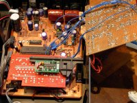
some piccies of work so far ") going to give it a good blasting for a while and then onto power supplies
going to give it a good blasting for a while and then onto power supplies
thanks everyone for your input and any and all suggestions welcome and will put more up when i do it
going to give it a good blasting for a while and then onto power suppliesthanks everyone for your input and any and all suggestions welcome and will put more up when i do it
Attachments

nos mod done tonite got some transformers on order and some rectifiers to chuck in power supplies, struggled soldering wires for some reason and i used cat5 cable for nos job but i think outer wiring was contaminating the so;der joint !!!! gonna strip it back a lot more and redo joints as they just look dodgy and put silicon sheives on after or is there a better cable to try
anthony
got some transformers on order and some rectifiers to chuck in power supplies, struggled soldering wires for some reason and i used cat5 cable for nos job but i think outer wiring was contaminating the so;der joint !!!! gonna strip it back a lot more and redo joints as they just look dodgy and put silicon sheives on after or is there a better cable to tryanthony
Looking good! You're braver than me attempting the decoupling caps - have you listened to it since that mod? I find a little flux really helps with those thin cat5 cables btw, you don't have to apply the heat for as long so you don't strip the insulation.
Sorry absolon - I've been away all week (pesky work). I bypassed those resistors but it really depends on your external supply as I think they offer some current limiting for the 1541. I'm no expert on this,I just followed the recommendations in the various 1541 based threads but I did find that providing an off-board supply supplying +3-4v more than needed feeding local regulators to drop to the required v worked out nicely.
I used used Oscons around the 1541 but I did it at the same time as the Clock and PSU mods so I can't vouch for their particular effectiveness! (not very scientific I know but the iron was hot!)
Cheers
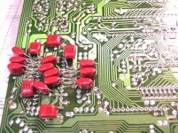
the first mod i done was the decoupling caps and i really struggled getting them in so it ended up a little untidy !!! perhaps some smaller caps would of helped and i ended up moving a couple so i could get the board in if i done the same again i would of put some silicon tube on legs which iv bought now, this really did seem to open the player up and seem less harsh ( like in a copied cd from a 60's recording harsh) i could certainly put up with listening to it if that makes sense and my only comparision is my cd67 marantz which was still a heap load better at that point, putting an earth on and grounding the clock seemed to improve things after that listening test, strangely changing the caps and diodes didnt appear to do any more but when i done the nos mod it really does appeal now and id say i like it above the standard cd67 i use and you can hear a really nice soundstage and other things my marantz doesnt put across as luckily i can have them rigged on the same setup at same time so comparision is easy !!!!
i would certainly do the caps on next player as there was a noticable difference and iv also fitted some 8 dil precision turned chip holders in and put some new opamps in and i do play the same cds after every mod and looks like the old marantz will be next in line for surgery but i really do like this old player now at quite high volumes
i redone my cables as to your advice josh and you can clearly see they are soldered properly now and that worked a treat and i only used plumbers flux !!! it worked my decoupling caps would certainly be put in better after all this soldering practice
ordered some 250v 3.3uf decouling caps and some other bits today and have really enjoyed the challenge !!! just dreading that it dont work moment which is sure to happen mucking around this much so baby steps and keep running and tseting after every move !!!
if i done the same again i would of put some silicon tube on legs which iv bought now, this really did seem to open the player up and seem less harsh ( like in a copied cd from a 60's recording harsh) i could certainly put up with listening to it if that makes sense and my only comparision is my cd67 marantz which was still a heap load better at that point, putting an earth on and grounding the clock seemed to improve things after that listening test, strangely changing the caps and diodes didnt appear to do any more but when i done the nos mod it really does appeal now and id say i like it above the standard cd67 i use and you can hear a really nice soundstage and other things my marantz doesnt put across as luckily i can have them rigged on the same setup at same time so comparision is easy !!!!i would certainly do the caps on next player as there was a noticable difference and iv also fitted some 8 dil precision turned chip holders in and put some new opamps in and i do play the same cds after every mod and looks like the old marantz will be next in line for surgery but i really do like this old player now at quite high volumes
i redone my cables as to your advice josh and you can clearly see they are soldered properly now and that worked a treat and i only used plumbers flux !!! it worked
my decoupling caps would certainly be put in better after all this soldering practiceordered some 250v 3.3uf decouling caps and some other bits today and have really enjoyed the challenge !!! just dreading that it dont work moment which is sure to happen mucking around this much so baby steps and keep running and tseting after every move !!!
Hi,
I don't really use it anymore, I got hold of a Mission 7000 which is pretty similar (especially after the mods) and I use that instead. There was a bit more room inside to do the mods and the display is nicer.
Mainly I replaced all the ecaps (including those on the board under the transport),added a clock, removed the 7220 to go nos, and added 3 new dedicated regulators for the 1541 and 2 for the opamps (replaced with LM 49720).
Regards
Pete
Looking good! You're braver than me attempting the decoupling caps - have you listened to it since that mod? I find a little flux really helps with those thin cat5 cables btw, you don't have to apply the heat for as long so you don't strip the insulation.
Sorry absolon - I've been away all week (pesky work). I bypassed those resistors but it really depends on your external supply as I think they offer some current limiting for the 1541. I'm no expert on this,I just followed the recommendations in the various 1541 based threads but I did find that providing an off-board supply supplying +3-4v more than needed feeding local regulators to drop to the required v worked out nicely.
I used used Oscons around the 1541 but I did it at the same time as the Clock and PSU mods so I can't vouch for their particular effectiveness! (not very scientific I know but the iron was hot!)
Cheers
Thanks Josh. I appreciate the benefit of your experience with the unit. I'm no expert either and had assumed the same about the resistors being for current limiting. After my successful experience with the 502, I think I will feed the resistors rather than bypassing. That will give me the option of using jumpers across the resistors to see if it makes any difference.
For now, I intend to use the existing supply up to and including the filter caps and add ten regulated, choke isolated low ripple supplies (overkill I'm sure, but I have a ten adjustable supply board already made up). How did you handle grounding for your off-board power supply? Did you disconnect the on-board transformer and use the board ground plane for the external supply or isolate the chip grounds to return to the off-board supply?
Chivvyp - yep they're a bit tight for room these players, hence mine eventually made it out into an mdf 'test-bed' contraption in the end (I got tired of having to undo everything to change a component. Both your's and mososgould's look a hek of lot neater than mine ever did!
Proper grounding wasn't something I ever got around to figuring out. IFIRC I started by just grounding the various supplies locally to the sections they were feeding (ie just under the 7220) I did leave the original trafo in place to power the control circuits but pretty much everything else had it's own (clock, 1541, output stage etc). I did ultimately re-arrange the grounding in a star, so one pick up point on the top side of the board for everything, I can't say I noticed a big difference though I'm afraid!
A good test for this maybe to play some low-level recordings with the volume up (as you would for testing the DEM clock when/if you get to that point). With a high volume and low level recording I could certainly hear some noise. I came to the conclusion ultimately that reducing noise on the power supplies/ground was a route to good sound!
I think that once you get to the point where the grounding scheme is starting to make a noticeable difference (as long as it it working properly and not dangerous!) then it maybe time to lift the 1541 and build a dedicated DAC board for it!
yes think your prob right josh and when i get round to fitting some dedicated power supplies i will run it for a while and then try taking nos back out to see what happens, with so much info available its a struggle working out whats best at times so im still trying to decide how to approach supply power build after reading so much
anthony
anthony
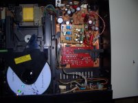
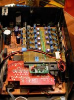
Here's another one.
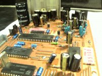
Stage one of the modifications included fresh capacitors, new schottky diodes for the 23 volt and 11 volt rectifiers, 4.7uF metallized polypropylene output coupling caps and replacing the LM833 op amps with LME49860.
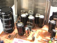
Stage two included adding ten new choke isolated, low ripple regulated power supplies based on LM317 and LM337 regulators to supply the DAC, the 7220 filter, the 7210 decoder and the RAM chip. The op amps also got their own individual supplies and are running at +/- 17V. AC is supplied by the original transformer. I also replaced 15 of the local bypass caps downstream of the regulators with higher capacitance Oscon SP solid aluminum caps.
Stage three will include wiring in the reclock module shown in the photo and replacing the DAC decoupling caps with 220nF polyester but won't be undertaken until I've had a good listen to stage two and done an A/B comparison with the other CD160 I have that has so far had stage one mods only.
Stage one of the modifications included fresh capacitors, new schottky diodes for the 23 volt and 11 volt rectifiers, 4.7uF metallized polypropylene output coupling caps and replacing the LM833 op amps with LME49860.
Stage two included adding ten new choke isolated, low ripple regulated power supplies based on LM317 and LM337 regulators to supply the DAC, the 7220 filter, the 7210 decoder and the RAM chip. The op amps also got their own individual supplies and are running at +/- 17V. AC is supplied by the original transformer. I also replaced 15 of the local bypass caps downstream of the regulators with higher capacitance Oscon SP solid aluminum caps.
Stage three will include wiring in the reclock module shown in the photo and replacing the DAC decoupling caps with 220nF polyester but won't be undertaken until I've had a good listen to stage two and done an A/B comparison with the other CD160 I have that has so far had stage one mods only.
Attachments


- Status
- This old topic is closed. If you want to reopen this topic, contact a moderator using the "Report Post" button.
- Home
- Source & Line
- Digital Source
- Philips CD-160 manual