Hi All, I got the service manual for mine here
It's a multipart download (free) so you need both parts. If you look closely you'll see Multipart: 0 1, just click on both to download both parts, unzipping one and opening the pdf will open both parts.
Cheers, Josh
Hi Josh, apologies, did download it, but on the Mac RAR is not standard
 so I downloaded several unzip apps from the app store. Didn't work, can't open.
 Anyway I have been cleaning up the opamp section and the i/V section. I will use the boards for a DAC.
albert
Thanks andy,
of course hard to read but the overall schematics helps a lot - i have been following the traces to get acquainted with this board.
For the DAC, I have one board already up & running with a CS8412; using the SAA7220 (so no NOS!).
I will have a separate supply for the 7220 with 0,2 F. Stabilizes the +5 there a lot.
I took out connections to pins 4, 6, 9, 10, 14, 15 (other trace than to the 1541), 22, 23.
attached the MSK to pin 11.
First look at the scope: it is a bit noisy (-80 db 5k hardly visible). I know how to improve: use real caps on the 1541 decoupling. So I'll see.
albert
cd160
just started ripping one of these to pieces and trying to learn about tuning cd players up but little to no knowledge of this stuff, have put an iec connector on back with inbuilt rfi filter and next i plan to fit toroidal transformers, would it be best to bypass the board dc parts and use an off board rectifier and also would anyone have a clearer manual and know best place to feed power supplies in to board for dac and motor etc as i can see on one drawing that there are a few power supply voltages,
also plan to do replace and add de coupling capacitors so any advice on what to use and where to use appreciated, even more so if you can say why in reply so a novice learns a bit hopefully.
thanks for any help
HI,
I've done pretty much everything you can do on this player eventually just using the DAC section on its own. It's the classis SAA7210-SAA7220-TDA1541 combination and as such, much of the information you can find on here for similar players can be applied to this.
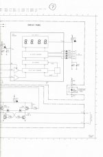
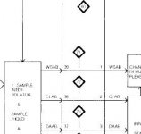
I'll post some more information when I get a chance but for now please see the attached DAC section for details on how to power the DAC part, it's just snips 1, 2 and 6 you need for the DAC, where
1 is -15v Supply
2 is +5v Supply
6 is -5v Supply
Building a supply for the above is tricky though and there's a lot to be said for having a second round of regulators right next to the DAC - it's a big topic this! Have a look on here for 'Ultimate TDA1541' I think most of the info is in there.
As with other players of this type you get a big easy win by providing the SAA7220 with it's own +5v supply.
I haven't got the schematics on this PC but there's a big thread here that goes into great detail! It's a slightly different player but a lot of the same rules apply.
Hope this helps for now
Cheers, Josh.
I've done pretty much everything you can do on this player eventually just using the DAC section on its own. It's the classis SAA7210-SAA7220-TDA1541 combination and as such, much of the information you can find on here for similar players can be applied to this.
I'll post some more information when I get a chance but for now please see the attached DAC section for details on how to power the DAC part, it's just snips 1, 2 and 6 you need for the DAC, where
1 is -15v Supply
2 is +5v Supply
6 is -5v Supply
Building a supply for the above is tricky though and there's a lot to be said for having a second round of regulators right next to the DAC - it's a big topic this! Have a look on here for 'Ultimate TDA1541' I think most of the info is in there.
As with other players of this type you get a big easy win by providing the SAA7220 with it's own +5v supply.
I haven't got the schematics on this PC but there's a big thread here that goes into great detail! It's a slightly different player but a lot of the same rules apply.
Hope this helps for now
Cheers, Josh.
Attachments
thanks
thanks for that josh and will look at getting a separate supply in as soon as possible and read all the other threads, suppose best thing is do one thing at a time and i am quite safe on high power electrics and panel wiring just never messed around with digital stuff but its fun learning
thanks for that josh and will look at getting a separate supply in as soon as possible and read all the other threads, suppose best thing is do one thing at a time and i am quite safe on high power electrics and panel wiring just never messed around with digital stuff but its fun learning
Hi
I think the quickest 'big win' mod for this player is providing the 7220 with it's own +5v supply - and it's dead easy to do.
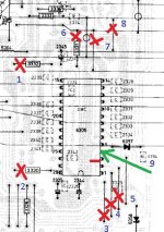
I've attached another pic - you can easily lift 3326 where indicated (you can see this also supplies the +5v for the DAC, just above the lift). By doing this your providing a clean supply for the 7220 and a much 'cleaner' supply for the DAC.
I just built a very basic +5v supply using an lm317 as per the lm317 datasheet, nothing special at all, I think I used a 9v torroid, followed by a recitifer and a heatsinked lm317 (it does get hot!), if you drop the voltage much more than that then you could add a pre-reg and spread the load!
As far as grounding - I think there is a nicely placed solder pad right underneath the 7220 - just ground to that or to one of the many top-side solder bridges.
Enjoy!
I think the quickest 'big win' mod for this player is providing the 7220 with it's own +5v supply - and it's dead easy to do.
I've attached another pic - you can easily lift 3326 where indicated (you can see this also supplies the +5v for the DAC, just above the lift). By doing this your providing a clean supply for the 7220 and a much 'cleaner' supply for the DAC.
I just built a very basic +5v supply using an lm317 as per the lm317 datasheet, nothing special at all, I think I used a 9v torroid, followed by a recitifer and a heatsinked lm317 (it does get hot!), if you drop the voltage much more than that then you could add a pre-reg and spread the load!
As far as grounding - I think there is a nicely placed solder pad right underneath the 7220 - just ground to that or to one of the many top-side solder bridges.
Enjoy!
Attachments
mods well start of them
just replaced decoupling caps around the dac to panasonic polyester types 0.1uf, installed a decent rf main filter, added a ground in from board to earth, changed mains cap on the on/off switch.
after a quick test run which i found had took some of the harshness away from the player i stripped board back out and grounded the top of the clock, even after such a small foray it sounded a different player, iv always used this to blast 70's rock and switch my marantz cd67se on for other music, also have a cd-101 in my setup as i enjoy my options with differing music.
ordered a few more parts for my next little play over the weeks and just taking small steps to start with and testing after every install, ordered some diodes and fm capacitors and will see where that takes it.
i did notice there are loads of de coupling caps on the back of board is it a good idea to change these to better ones ie de coupling on capacitors, diodes etc and i must find a manual somewhere.
thanks for inspiration josh and at least the player survived and will put some piccies on here when i get chance and also get my head around why im doing things which is the hardest thing with so many differing oppinions on whats best to do its hard for a novice to work it all out !
anthony
... I think the quickest 'big win' mod for this player is providing the 7220 with it's own +5v supply - and it's dead easy to do....
The quickest 'big win' mod for this player is to replace the 7220P/A filter with the 7220P/B. Just my two eurocents
")
Good point elektroj - I'd forgotten all about swapping that! I think they can still be had on ebay for a few pounds
There are plenty of opinions about those decoupling caps under the TDA, but I never did get around to changing them. I figured what I gained in higher quality caps I might lose in having longer lead lengths, plus it's a tricky job changing them. For the trouble you may be better off building a dedicated board for the DAC part, it's a fairly simple layout (at least to match the existing one) and as long as you socket the TDA you can try a variety of decoupling caps & localised PSU combinations.
I found that the PSU's arguably had the biggest effect, followed closely by the output stage modifications (plenty of choice there as well!), then the clock upgrade but that's probably a result of the order in which I did them. I didn't have quite as much success with cap replacement with the exception of the large caps on the TDA PSU (close to the chip), I could be wrong but the quality of these seem to matter.
If you look after the 1541 and especially the transport itself then you can't go far wrong, trying out a variety of mods until you find a combination that works. Before applying any PSU mods I would socket the 1541 and the 7220 then check the voltages at the sockets before(!) putting the chips in (I killed my 7220 by applying too higher a voltage to it I think).
Have fun!
cd160
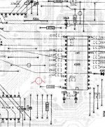
well didnt take me long !!! was gonna replace the two small electrolytic caps with some decent ones after changing quite a few caps and making good progress 1uf and 3.3uf and lost my bit of paper so forgotten which went where, looked at a schematic iv got and it shows the one as next to decoder position 2311 as 10uf and doesnt show the other one at all so think i need the right schematic so i dont dig a deeper hole or im looking at drawing wrong, missing one is by dac off trace 28 jumpers across with 3330 and theres a capacitor from that track to three tracks across.
hope that makes sense if someone can help and sure i will be asking again in no time flat !!! beginners
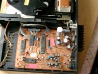
Hi - not sure where you mean. The rail that Dac pin 28 connects to via 3330 is the 5v supply. There should be a cap (2325 - 47uf) from pin 28 to ground with an smd underneath. Just to the right of that is another (2344 - 47uf) from pin 26 to ground, this also has an smd but its under the dac.
Any chance of a photo?
Any chance of a photo?
cd160
hi yes no probs thanks i was stopping myself before i made a mess !!! will do homework a bit better next time and check stuff exists and what it does a little more before storming in marked them on attatchement in red but this is just a stock net piccie
thanks
hi yes no probs thanks i was stopping myself before i made a mess !!! will do homework a bit better next time and check stuff exists and what it does a little more before storming in
marked them on attatchement in red but this is just a stock net picciethanks
Attachments
hehe - no wonder, that bottom ones not on the schematic! I'll check my board......nope, I haven't got one there either! That said, mines an early board (I think) and has a separate PCB in place of the middle decoder (something to do with there being a bug in early chips IIRC).
The top one is 2311 (50V 10uf).
The bottom one, near the DAC - If the end near the DAC is connected to the +5v rail then it would seem to decouple it to the word select line between the two decoders. Unlikely though, I can't see why this would be beneficial.
That said, on the photo, it looks like it doesn't connect to the +5v, but to another pad near it - I've just checked by board again and I have pads where that capacitor would be but they connect to......nothing. My guess is that it could be used to decouple the WS to ground, either way, I don't think there's any harm in leaving it out. I don't remember seeing this on any similar schematics either!
Maybe someone who has a board with this in place could shed some light?
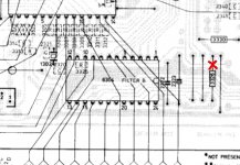
This is where I think the Cap is (in red), looking at other photo's as well. On mine, the four pads on pcb connect to each other but nothing else! Very odd...as you can see there is no pad on the +5v line. The schematic itself also shows a direct connection between pin 39 of the 'A' chip to Pin 1 of the 'B' chip, no mention of a cap there either.....
Attachments
Last edited:
thanks josh
how i managed that i dont know but lesson learnt and at least i stopped myself at a unthinking moment !!!! i do know the two caps i took out are 1uf value and 3.3 uf value 50v i beleive and yes perhaps someone will give some advice on upgrades or why they are there, i had ordered some exact caps to put back in.
thanks for your patience and help
Good stuff! Typical 1980's philips from what I understand! Mine has the uP panel (the extra board in place of the MAB8441P/T012) and on the schematic there is a star next to 2319 with a note saying 'Not present in sets with a uP panel' so there we are, mystery solved! I do have a 2311 though but it's a 10uf, I think this has something to do with a filter for the VCO(!) a bit over my head to be honest! I suspect this values important though!
changed all the power caps today and put original values back in with those two and all is working properly !!!! hopefully someone may enlighten those two caps a little better for poss upgrading
sounding a load better with new caps and decoupling on chip but think im gonna run it as it as for a few weeks just so i notice the next round of upgrades properly like separate power supplies etc as you suggested josh
thanks for help again
sounding a load better with new caps and decoupling on chip but think im gonna run it as it as for a few weeks just so i notice the next round of upgrades properly like separate power supplies etc as you suggested josh
thanks for help again
Hey Josh, I'm in the middle of some changes on my CD160 and just got to the point where I'm working out the details on individual power supplies and have a couple of quick questions if you don't mind.HI,
I've done pretty much everything you can do on this player eventually just using the DAC section on its own. It's the classis SAA7210-SAA7220-TDA1541 combination and as such, much of the information you can find on here for similar players can be applied to this.
I'll post some more information when I get a chance but for now please see the attached DAC section for details on how to power the DAC part, it's just snips 1, 2 and 6 you need for the DAC, where
1 is -15v Supply
2 is +5v Supply
6 is -5v Supply
Building a supply for the above is tricky though and there's a lot to be said for having a second round of regulators right next to the DAC - it's a big topic this! Have a look on here for 'Ultimate TDA1541' I think most of the info is in there.
As with other players of this type you get a big easy win by providing the SAA7220 with it's own +5v supply.
I haven't got the schematics on this PC but there's a big thread here that goes into great detail! It's a slightly different player but a lot of the same rules apply.
Hope this helps for now
Cheers, Josh.
First, on the attachment you posted with the DAC supply connections you indicate +15V connection to Pin 28. Is that a typo? The DAC datasheet indicates that Pin 28 gets a +5V supply so that is what I'd intended on supplying but I'm working with best guess and would rather not get it wrong.
Second, are you supplying power through the resistors or bypassing them and supplying direct to the chips? I've read that power should be supplied through them and was successful using that method on a CDB 502 I did a trial run on but again, I'm unsure whether that is the better way to go.
Third, what did you use for the capacitors supplying the various chips you repowered. I've acquired a variety of higher capacitance Oscon SP for those locations but am curious what you did and what your results were.
Fourth, I've not read about replacing the 7220/A filter with the 7220/B. What is the reasoning for this change?
I have two of these dedcks and have done a full recap, resoldered all the griplett connections, installed schottky diodes to rectify power, replaced output coupling caps with film and swapped opamps on both. I've also successfully replaced the 2/10 laser swing arm assembly on one with a 4/19 arm to replace a laser that failed from overcurrent. Current plans are chip repowering using stable regulator circuits and installing a reclock module on one to see what further improvement can be made.
Thanks for your comments.
- Status
- This old topic is closed. If you want to reopen this topic, contact a moderator using the "Report Post" button.
- Home
- Source & Line
- Digital Source
- Philips CD-160 manual